Diagnostics
AM700 Audio Measurement Set Service Manual
6–35
l. If any “critical” errors occur, jump back to the startup code.
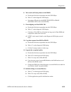
2. Read the DRAM size bits from the Board Status Register (BSR).
a. Encode the 8-bit boot step number into the USP LSByte.
b. Write “2” on the diagnostic LED display.
c. Read the DRAM size bits from the Board Status Register.
3. Initialize the DRAM controller.
a. Encode the 8-bit boot step number into the USP LSByte.
b. Write “3” on the diagnostic LED display.
c. If DRAM status bits indicate 16 Meg is present:
Write 0 to address 0x42b20980 to initialize the DRAM Controller for
16 MW.
Else (assume 8 Meg present):
Write 0 to address 0x40b20980 to initialize the DRAM Controller for
8 MW.
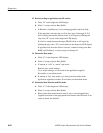
d. Test for presence of the DRAM.
Do a 32-bit read at address 0x30000100.
Write back the inverse of what was read.
Precharge the bus by writing what was read to the diagnostic LED
address, 0x18000000, and waiting a while.
Do another 32-bit read at address 0x30000100.
If the same data as the first read is returned, no DRAM was found.
Flash “3” on the diagnostic LED display –several– times.
Jump back to the startup code.
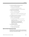
Since a location that may not yet have been written is being read, there
can be a parity induced access error (exception 2) here if the Board
Program Register fails to mask parity exceptions. There may also be a
bus error induced access error from the reads or writes to DRAM. It will
be necessary to physically probe the hardware to determine the actual
cause.


