


Diagnostics
AM700 Audio Measurement Set Service Manual
6–43
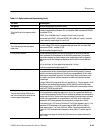
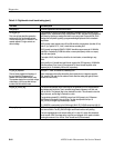
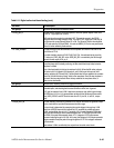
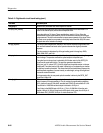
Table 6–11: Digital audio circuit board testing (cont.)
Test name Test description
Test group 2 Generator adjustments and functional checks.
2.1 adj_synth_1
This is the first pll of the frequency offset
circuit.
Locks pll 1 to 12.288 MHz. Operator adjusts L5 to give correct vco control voltage. Pll 1
consists of programmable synthesizer U81, error amplifier U39B, resonant tank CR16/L5,
and oscillator IC U78.
OFFSET_IN is 12.288 MHz from Y1, through U115 pin 5 and U114 pin 36.
Serial control lines OFFSET_SEL0 and OFFSET_SEL1 (U96 pins 7 and 6) – must both
be low to route this clock through U114 and U115.
2.2 adj_synth_2
This is the second pll of the frequency
offset circuit
Pll 2 locks to pll 1, so pll 1 should be verified first with test 2.1. Adjust L7 to give correct
vco control voltage. Pll 2 consists of programmable synthesizer U82, error amp U39A,
resonant tank CR18/L7, oscillator IC U79.
Buffer Q4 amplifies the signal from pll 1.
2.3 freq_offset_response This test alternately programs plls 1 and 2 to generate 8.192 MHz and 12.288 MHz.
(These are master clock frequencies for 32 and 48 kHz sample rates.) The operator
observes the changing vco control voltages on an oscilloscope to check for expected
settling time of a few ms. Settling time depends on the R’s and C’s around U39A and
U39B.
If pll 1 is out of spec, pll 2 can appear to be bad until pll 1 is fixed.
The plls are programmed serially through U117.
2.4 freq_offset_unlock_flag This test checks that the out-of-lock flags for pll 1 and pll 2 are operational. Pll’s 1 and 2
are programmed for 48 kHz, allowed to settle, and the unlock flag cleared. The unlock
flag then is checked to verify initial lock. The pll’s are re-programmed for 32 kHz, which
causes them to momentarily loose lock. The unlock flag is read to verify that the out of
lock condition was latched, and then cleared and re-read to verify that lock has been
re-established.
The flags, LD0 and LD1, originate at U81 pin11 and U82 pin 11. They are latched in U102
where the two are combined into one output, SYNTH_UNLOCK, which the 56k reads
serially through U94 pin 4. SYNTH_UNLOCK from U102 pin16 is cleared under software
control by ER_CLEAR from U96 pin15.
2.5 freq_offset_range
This test checks that the VCOs in pll’s 1
and 2 can be tuned to the minimum and
maximum required frequencies.
The default clock (12.288 MHz) drives pll 1, which is programmed to generate 6.39 MHz.
Pll 2 is programmed to multiply the output of pll 1 by one, so it generates 6.39 MHz also.
This is the lowest frequency that the VCO’s are expected to generate, and corresponds to
a sample rate of 25 ks/s. The out-of-lock flags are checked to see that the plls are locked.
The test is then repeated with pll 1 programmed for 14.87 MHz, which is the highest
frequency the VCO’s must generate, and corresponds to a sample rate of 58 ks/s.
The frequency of pll 1 VCO is set by CR16 and L5. Coil L5 was adjusted in step 2.1. The
capacitance of CR16 depends on the output voltage of U39B. At 25 ks/s, U39 pin 7
should measure about –1 to 0 volts. At 58 ks/s, U39 pin 7 should measure about 9 to
10 volts. Pll 2 VCO is identical and its frequency is set by CR18, L7, and the output of
U39A.
Note that the minus supply for dual op-amp U39 comes from a resistive divider and is
about –3 volts.