


Removal and Replacement Procedures
AM700 Audio Measurement Set Service Manual
6–85
10. Repeat for the other backlight.
11. Connect the backlight connectors to the inverter boards (or board for the
earlier version).
NOTE. Step 12 is not needed for the newer assemblies because it is not necessary
to remove the inverter boards to disconnect and reconnect the backlight
connectors. Go to step 13.
12. Align the inverter board with the standoffs on the rear shield and install the
two screws to reattach the inverter board to the shield.
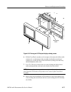
13. Position the LCD flat panel back in place and align the four corner holes
with the standoff on the rear shield.
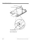
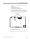
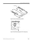
14. Reroute the touch screen cable under the LCD flat panel and install the four
screws to hold the flat panel to the rear shield. Reconnect the grounding wire
at the screw shown in Figure 6–43.
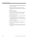
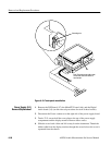
15. Replace the touch screen with metal frame over the LCD panel as shown in
Figure 6–43. Use care to keep the touch screen cable in the slot in the metal
frame (as shown for the early versions of touch screen) so as not to pinch it
between the metal frame and the rear shield. Use the end of the touch screen
cable coming from underneath the LCD flat panel as a guide to assist you to
keep the cable in the slot as you place the touch screen over the LCD flat
panel.
16. Reinstall the LCD assembly into the instrument. Refer to the LCD Assembly
Remove and Replace procedure on page 6–76 for directions.