


Theory of Operation
AM700 Audio Measurement Set Service Manual
3–33
+22 V
–22 V
–15 V
+15 V
+5 V
OVLD
From
Output
Amplifiers
Floating
Power
Supply
Opto-Iso.
Opto-Iso.
8 X
Oversampling
Hi Res
Hi BW
Sync and
Delay
Hi Res
Hi BW
20-bit/18-bit
DAC
Ch A +
Ch B+
To Front Panel
Output Z
Selector and
Post Attenuator
Ch A +
Ch B–
Output
Ampl.
Output
Ampl.
OVLD
OVLD
Ch A
Ch B
Channel A
and Channel B
Gain/
Attenuator
HiRes
Low Distortion
Mode Filter
Ch A
Ch B
OVLD
To DSP
Ch A
Output
Selector
Low Distortion On/Off
2
Hi Res/Hi BW
Ch A
Ch B
To Acquisition
Hi Res
Low-Pass
Filter
Hi BW
Low-Pass
Filter
Hi Res
Hi BW
Ch B
Ch A
Ch B
Ch A
Ch B
Hi Res
Hi BW
To Output
Data Selector
Output Z
Selector and
Post Attenuator
Ch A
Ch B
DSP
Section
ONCE
Port
(Development)
Referenced
Ground
Floating
Ground
To
CPU
Host Bus
From
Power
Supply
+22 V
–22 V
To Generator Floating Circuits
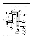
(The floating power supply in on the analog generator board in the
CRT display instruments. It is on the power supply board in the flat-panel
display instruments)
+5 V
12.228 MHz
Right and Left Digital Audio Data
2
2
Clocks
Serial
Control
Opto-Iso.
Right & Left
2
Opto-Iso.
Frame
Std
12.228 MHz
BClk
Clocks
Ch A –
Ch B+
Ch A –
Ch B–
Output
Clamp
Output
Clamp
12
U9,U10
U94
345
6
7
8
9
Opto-Iso.
U20,U21
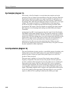
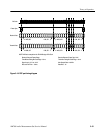
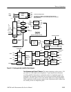
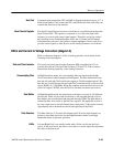
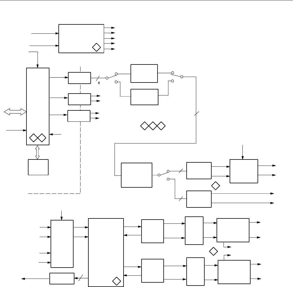
Figure 3–11: Analog generator simplified block diagram
Post Attenuator and Output Z Selector. The output impedance at this point is 5 W
per side for a 10 W output source impedance. A post amplification attenuator
providing 42 dB of attenuation is switched in when low amplitude signals are
generated. This attenuator reduces the level of noise associated with the output
amplifier so that the signal to noise ratio remains high at low output amplitudes.
Direct application of the generator signals to the Acquisition board is taken from
the circuitry at this low impedance point.