


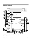

Theory of Operation
3–4
AM700 Audio Measurement Set Service Manual
rectifier acts as a full-wave bridge rectifier; for 115 V operation, the primary
rectifier is configured as a full-wave voltage doubler.
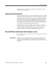
The primary bridge rectifier is protected by the mains line fuse and surge
suppressors. A mains line filter at the input of the power supply reduces
conducted and radiated EMI from and to the AM700. Additional components in
the rectifier output provide line filtering and common-mode noise rejection for
further reduction of conducted electromagnetic interference. Input surge current
and overvoltage protection components are included in the input rectifier circuit
to prevent major component damage in the event that incorrect line voltage is
applied to the AC input.
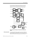
Housekeeping Supply. A second power supply provides the housekeeping (or
keep-alive) power source. This supply provides power to the logic circuitry that
controls the power supply STBY/ON logic circuitry. It is supplied through a
transformer that is wired with the power line switch to provide the correct
voltage to the primary for either line voltage. The rectifiers for the + and –14.5 V
housekeeping supply are full-wave with capacitive filtering of the rectified
voltages. The filtered voltages are regulated by 3-terminal regulators. Both sides
of the transformer secondary are fused with self-healing fusing devices. One of
the sensing signals (LINE SENSE) to the power supply logic circuitry is
developed from the secondary of the housekeeping supply transformer.
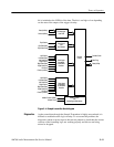
Floating Power Supply. In CRT display instruments, these supplies are located on
the Generator board (A5). In LCD flat panel display instruments, the floating
supplies are part of the power supply board.
The floating power supply provides the isolated voltages to power the analog
audio generator. This isolation permits the generator outputs to float with respect
to chassis ground. The +22 V and –22 V outputs of the power supply power a set
of 3-terminal regulators that provide the +15 V, +5 V, and –15 V to the Generator
board. Those voltages, along with the +22 V and –22 V voltages and the floating
return line are connected to the Generator board through J12 on the power supply
board.
AM700 Circuit Description
The remainder of this section provides more information regarding circuit
operation of the AM700. It is arranged by assembly (board number) and follows
the schematic diagram in order. Refer to the appropriate schematic diagram in the
diagrams section to follow the circuit descriptions. Simplified block diagrams
are provided in the circuit descriptions. Diamond symbols in the blocks indicate
the schematic diagram or diagrams associated with that functional block. More
detailed block diagrams are also included in the diagrams section of this manual.