Rack Adapter Instructions
6–94
AM700 Audio Measurement Set Service Manual
Extra hardware is provided with the slide-out track assemblies. Since the
hardware is intended to make the tracks compatible with a variety of cabinet
racks and installation methods, not all of the hardware will be used for any
installation procedure.
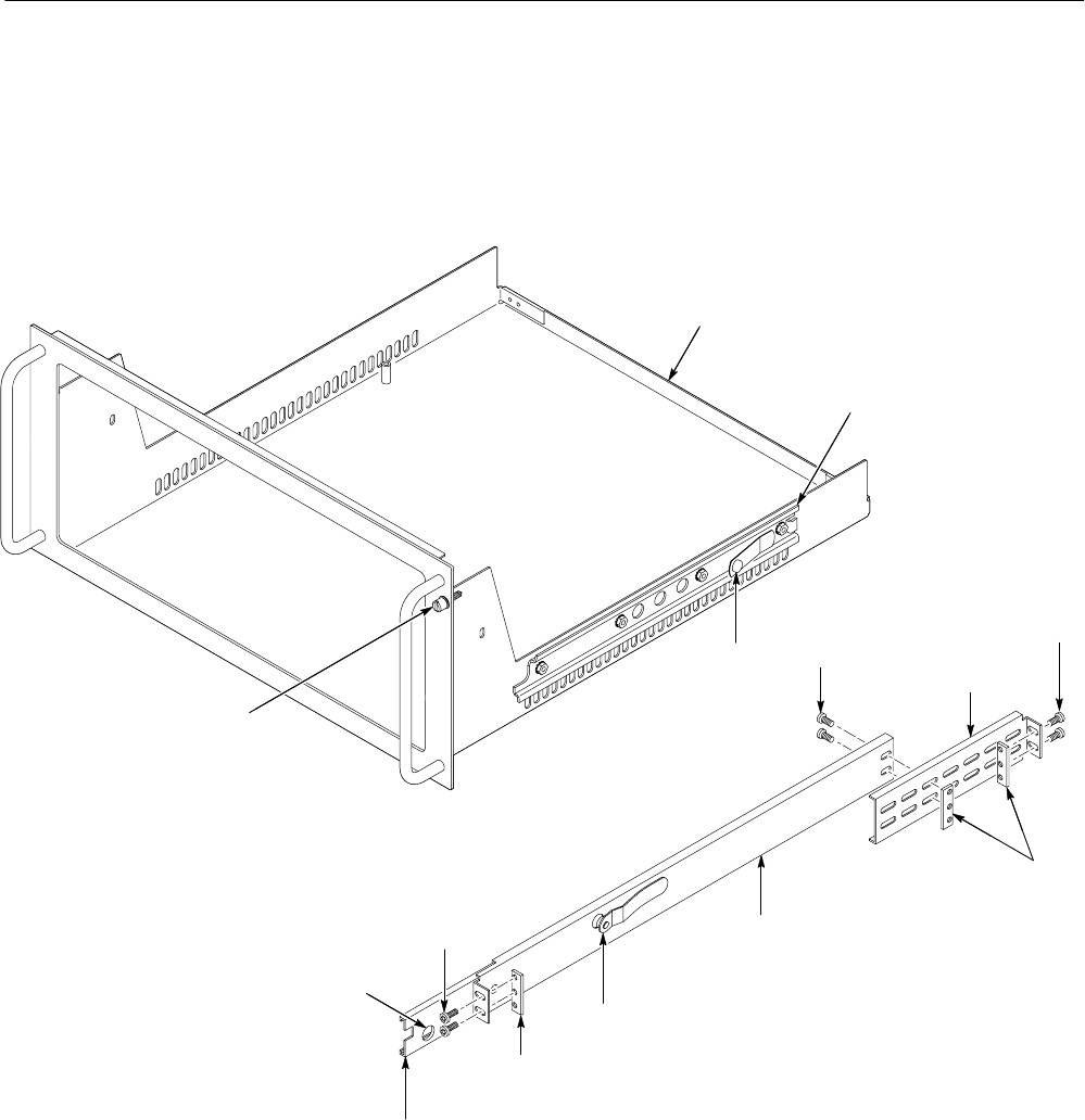
Chassis
section
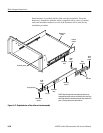
NOTE: Right-hand and left-hand stationary sections are
designated by the RH and the LH marked on the rails. Stop
latch holes should be towards the bottom when slides are in
place. (The right hand rail is shown above.)
Retaining screw
Rackmount
cradle
Intermediate
section
Stop latch hole
Rear
mounting
Bar nuts
10-32
PHS
screws
Bar nut
10-32
PHS
screws
Automatic
latch
Stationary
section
Automatic
latch
10-32
PHS
screws
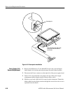
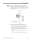
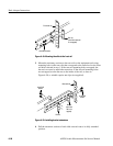
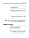
Figure 6–47: Exploded view of the slide-out track assembly


