


Theory of Operation
3–52
AM700 Audio Measurement Set Service Manual
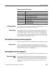
This Register is composed of four 8-bit registers, U86, U88, U92, and U125. The
register bit states indicate various board status and control various board
operations on the HOST CPU side. Its contents can be written and read. A bit
mapping of the registers with signal names and descriptions of bit values is given
in Table A-14 in Appendix A.
This register, U78, holds the switch settings of dip switch S2.
The DS1286 device is a real time clock is used to keep track of the ‘real time’
and time-related activities. It comes with 50 bytes of user NVRAM. It contains
an embedded lithium cell that can maintain data and real time for over ten years
in the absence of Vcc. Refer to the manufacturer’s data book for detailed
information on this device.
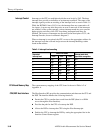
Timer Registers and Addresses. Table A-15 of Appendix A lists the cross
references of the Timer Registers and their addresses.
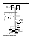
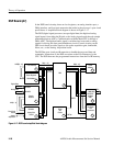
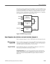
I/0 Processor (diagram 7)
Refer to schematic diagram 7 of the A6 CPU board for the following discussion.
The Front Panel Processor, U110, handles all of the front panel controls, and
through the Floppy Disk Controller, U105 (diagram 9), the data transfers to and
from the floppy disk drive. Two clock signals are applied to the Front Panel
Processor: the serial port clock, 3.6864 MHz, and the processor clock,
16.667 MHz. The processor clock must have a 4 V swing and a 50% duty cycle.
A flip-flop, U121A, divides the 33.3333 MHz output of Y7 by two and buffers
the signal. The output of the flip-flop has a nearly 50% duty cycle as needed by
the processor.
The Front Panel RAM, U108 and U109, store the operating instructions for the
I/0 Processor. These instructions are downloaded from the CPU at power up and
whenever a new front-panel description is needed. Access to this shared memory
is handled through a Bus Request/Bus Grant routine.
The bus interface between the 16-bit Front Panel Processor data bus and the
32-bit CPU data bus is handled by buffers U94, U95 ,U96, and U97. Data is
transferred between the two busses in 16-bit words. The two sets of buffers are
enabled to select which 16-bits of the CPU long word are selected for transfer.
Board Program Register
(BPR)
Board Code Register
Real Time Clock
Front Panel Processor
Front Panel Processor
RAM
CPU to Front Panel
Interface Buffers