


Theory of Operation
3–32
AM700 Audio Measurement Set Service Manual
Analog Generator Board (A5)
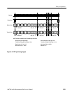
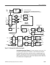
A simplified block diagram of the analog generators is shown in Figure 3–11.
The following block diagram description explains the blocks from a functional
point of view. The schematic diagram description is given later.
There are two analog generators: High Resolution and High Bandwidth. The
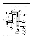
simplified block diagram is shown in Figure 3–11. An expanded block diagram
of the DSP section of the generator is shown in Figure 3–12. Each generator has
two channels of output. The High Resolution generator output channels are
independent and can output completely different signals on either channel. The
High Bandwidth Generator outputs the same signal on both channels.
Portions of the analog generator circuitry are floating and require a floating
power supply to provide the operating voltages. Floating the generator helps
break ground loops in a system composed of the generator, a device under test,
and the analyzer. Prior to the flat panel display version of the AM700, the
floating power supply was located on the generator board. With the flat panel
display circuitry installed, the floating power supply is on the power supply
board. Data and control signals between the floating and nonfloating portions of
the circuitry are passed through opto-isolators.
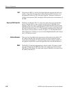
DAC and Filtering Circuits. The high resolution data is 8 X oversampled before
being applied to the right and left DAC for Ch A and Ch B analog signal
conversion. The high bandwidth data passes through a sync and delay circuit to
properly align the data for conversion. The DAC current output signal is
converted to an analog voltage signal and filtered by the appropriate filter circuit.
The high resolution signal path also contains a Low Distortion Mode filter that is
selectable for use when lower signal distortion is needed from the analog
generator.
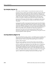
Output Amplifiers. The output amplifiers have a positive and a negative amplifier
section to produce the differential audio output signal. Each channel amplifier
has an overload detector that senses an overload condition. If an overload occurs,
and OVLD signal automatically switches in additional attenuation to protect the
output amplifiers. The OVLD signal is also applied back to the DSP section for
processing. The outputs of the amplifiers are protected by a clamp circuit that
prevents an external voltage condition from damaging the output amplifiers.
Block Diagram
Description of the Analog
Audio Generators