


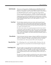

Theory of Operation
3–2
AM700 Audio Measurement Set Service Manual
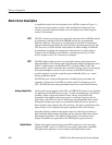
Block Circuit Description
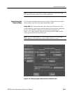
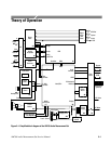
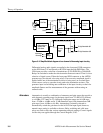
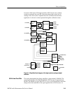
A simplified board-level block diagram of the AM700 is shown in Figure 3–1.
Only the main signal paths are shown. More detailed block diagrams of the
circuitry are shown with the detailed circuit descriptions and in the diagrams
section of this manual.
The CPU (central processing unit) controls the operation of the AM700 using the
programming contained in the flash EPROM (electrically programmable
read-only memory). That memory is programmed at the time of manufacture
with the standard programming plus any optional programming purchased. The
CPU has access to all the devices on the busses for either reading of the ROM
programming or reading and writing to the other devices for either memory
storage (to the NVRAM or other RAM) or controlling the activity of other
devices (output to the VGA connector for example).
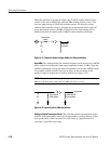
The DSP (digital signal processor) accepts digital analog signal inputs from
either the Digital or the Analog input boards through sample transmitter/receiver
ASICs. Communication with the Main/CPU is through a DMA ASIC. The
digitized audio signal is serialized and converted to analog signals for driving the
front panel headphone circuit. Control circuitry on the DSP circuit board
provides signals to set up the acquisition gain, bandwidth, filters, etc., on the
Analog Acquisition board.
The DSP has port A and port B memories to handle the processed data and
commands. Instructions to the DSP are written to the Port B memory by the
CPU. The DSP then runs the programmed instructions for the Port B memory.
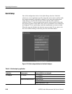
Analog audio signals applied to the CHA and CHB XLR connectors are digitized
for application to the DSP for processing. A small over/underrange circuit board
assembly, which is physically attached to the Analog Acquisition board,
determines if the applied analog input signal is overrange (signal too big for
application to the A/D converter) or underrange (signal amplitude that is small
enough that a higher gain step or less attenuation should be used to provide a
better dynamic range signal to the A/D converter). The gain or attenuation of the
input circuitry is set to optimize the signal amplitude to the A/D converter.
Selectable filtering conditions the applied signal for either high resolution or
high bandwidth measurements depending on the selections made from within a
measurement application. The digitized input signals are formatted by the
Sample Transmitter for application to the DSP (digital signal processor).
Digital audio signals from the front panel XLR connectors or the rear panel
connectors (BNC, optical, or, XLR) are processed for application to the DSP.
The digital audio generator is also located on the Digital Audio board.
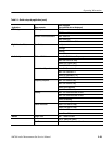
CPU
DSP
Analog Acquisition
Digital Audio