


Theory of Operation
3–42
AM700 Audio Measurement Set Service Manual
A Channel and B Channel signals from the stepped attenuators are applied to
buffer amplifiers U27A (A Channel) and 28A (B Channel) to isolate the stepped
attenuator stage from the output amplifiers and provide three gain ranges. The
gain of these amplifiers is separately controlled by more 1-of-8 data selectors in
the inverting input of the amplifiers (U29 in A Channel and U30 in B Channel).
The input resistance and feedback resistance is selectable to provide unity,
+6 dB, or +12 dB of gain for the amplifier in each channel.
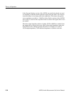
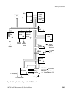
A and B Output Amplifiers and Output Z Selectors (diagrams 7 and 8)
Refer to schematic diagram 7 and schematic diagram 8 of the A5 analog
generator circuit board for the following circuit description.
The A and B Channel output amplifiers are identical in circuitry and operation.
The single-ended channel signal is applied to the inverting input of the buffer
amplifiers in the A and B Output Amplifiers (U49A and U55A respectively)
circuitry. This inversion in the operational amplifier makes the overall amplifier
be noninverting. The feedback signal is applied to the noninverting input of the
input buffer amplifiers. A selectable feedback resistance is used to provide two
overall gain settings for the output amplifier: unity and +6 dB. Each of the
output amplifiers has a complementary-symmetry circuit arrangement to form a
push-pull amplifier stage.
The differential output signal from the analog generator is produced by applying
the output of noninverting half of the output amplifiers to a second, almost
identical, unity-gain inverting amplifier whose output is the differential signal to
the output of the noninverting half of the amplifier.
In the flat panel display version of the AM700, two small relay boards are used
to completely isolate the internal generator signal from the cable to the Acquisi-
tion board when it is not being sent to the acquisition. This reduces the genera-
tor-to-acquisition crosstalk to –140 dB or below. Earlier versions of the AM700
used a relay T-switch on the Acquisition board to shut off the signal when it was
not needed.
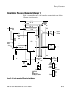
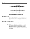
Overload Protection. If the output of either half of any output amplifier becomes
overloaded, the voltage across the resistor in the output transistor of the amplifier
increases to a level that turns on the LED of the Overload Indicator opto-isolator.
The output of an active opto-isolator triggers a one-shot multivibrator. An
overload indication will usually occur at the peak of the signal for a short
duration of time.
The one-shot is used to lengthen the output pulse to permit time for the overload
condition to be sensed by the processor. There are two outputs from the one-shot.
One sets an Enable flag that is sensed by the processor. When the flag is set, a
warning indication is displayed to warn the user that an overload condition exist.
A and B Channel Buffers
A and B Output Amplifiers