Adjustment Procedures
5–6
AM700 Audio Measurement Set Service Manual
This procedure is provided for factory service to check for proper operation to
determine if repairs or adjustment are needed.
The following test equipment is needed to verify and adjust the power supply:
H Test oscilloscope with 1X probe
H Digital voltmeter
H Universal load unit
1. Remove the power supply from the AM700 and connect it to the power load
unit.
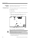
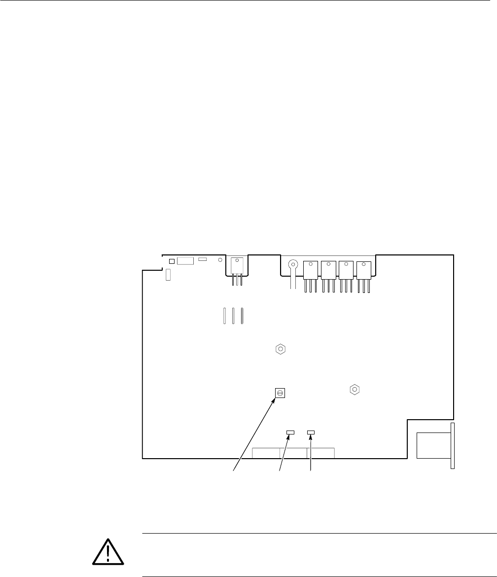
2. Connect the plus (+) lead of the DVM to TP25, +5 V, and connect the
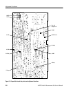
ground (–) lead to TP4 (analog ground) (see Figure 5–1).
J6
J10
J5
J11
CR26
Q2Q3Q6Q7
A GND+5 V Adjust +5 V
J9 J8 J7
FL1
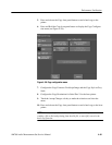
Figure 5–1: Power supply +5 V test points and adjustment locations
CAUTION. Make sure the Line Selector switch is set to the correct operating
voltage range before applying power to the supply. The power supply can be
damaged if operated with the incorrect voltage range.
3. Slowly increase the voltage to the power supply to the nominal mains supply
level (115 Vrms on low range or 230 Vrms on high range) to determine if the
power supply is operating normally.
Factory Service
Adjustment
Test Equipment Required


