


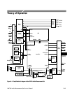

Theory of Operation
AM700 Audio Measurement Set Service Manual
3–5
Schematic diagrams are numbered sequentially by circuit board, for example,
A5 diagram 3 and A6 diagram 3.
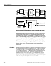
Analog Acquisition Board (A1A1)
Analog audio signals applied to the CHA and CHB XLR connectors are digitized
for application to the DSP for processing. A small over/underrange circuit board
assembly, that is physically attached to the Analog Acquisition board, determines
if the applied analog input signal is overrange (signal too big for application to
the A/D converter) or underrange (signal amplitude that is small enough that a
higher gain step or less attenuation should be used to provide a better dynamic
range signal to the A/D converter). The gain or attenuation of the input circuitry
is set to optimize the signal amplitude to the A/D converter.
Selectable filtering conditions the applied signal for either high resolution or
high bandwidth measurements depending on the selections made from within a
measurement application. The digitized input signals are formatted by the
Sample Transmitter for application to the DSP (digital signal processor).
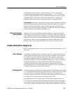
CHA and CHB Input and Attenuator Boards (diagrams 1 and 2)
Refer to schematic diagrams 1 and 2 of the A1A1 circuit board for the following
circuit description.
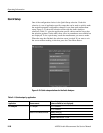
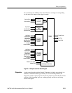
The Channel A and Channel B Input circuitry are identical in operation. The
Channel A circuitry is described. Like components in Channel B perform the
same function. A simplified block diagram of the analog input circuitry is shown
in Figure 3–2.
Analog Inputs