9–14
AM700 Audio Measurement Set Service Manual
U24 drives U20 and U21 (Buffer))
though R30 – R33 (Values are Critical)
44 4
4
4
3
12.288 MHz CLK
FRAME
STD (DATA)
B CLK
From Digital Section
A
A
Digital Ground
Floating
Analog
Ground
U20,U21
U22,U23
U40 – 42
U96
U16
U39 (U38)
U18 U19B
U13BU15
–15V
+15V
+5VI
–5VI
DAC Voltage
Regulators
High BW/High Res
Opto–
Isolators
8X Digital
Oversampling
Filter
Invert
24–Bit Data Delay
Select
B CH
A CH
Current
to Voltage
Converter
Current
to Voltage
Converter
+ Delay
Right DAC
20–Bit
Left DAC
20–Bit
High Resolution Path
High Bandwidth Path
TP32
B DAC
B DAC
TP31
A DAC
A DAC
R24
DAC
Gain
R18
DAC
Gain
20 Bits to 20KHz
or 16 Bits to 80KHz
(monaural only)
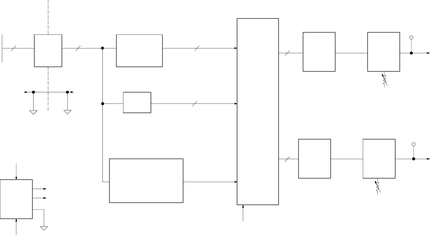
Figure 9–10: Analog generator DAC and current-to-voltage converters


