Adjustment Procedures
5–4
AM700 Audio Measurement Set Service Manual
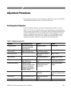
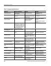
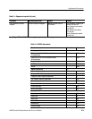
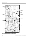
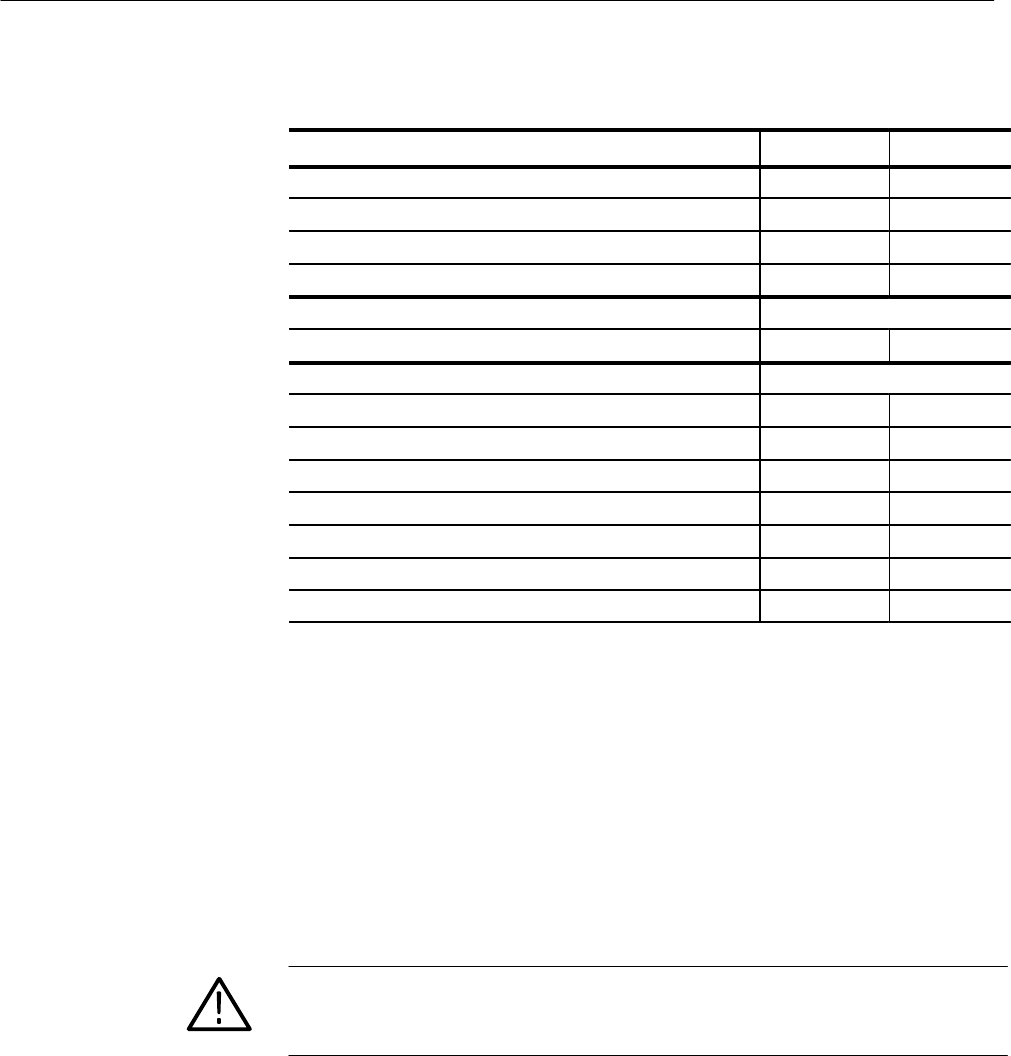
Table 5–2: AM700 adjustments (cont.)
Board name Circuit no.Circuit board
Vertical Size R45
Horizontal Hold R20
Horizontal Phase (centering) R15
Trace Rotation R67
Power Supply A11
+5 V Adjust R14
LCD Driver Board A13
Red Offset (omitted) R37
Green Offset (omitted) R39
Blue Offset (omitted) R41
Red Gain F6
Green Gain R7
Blue Gain R9
BRT R24
Preparation for Adjustment
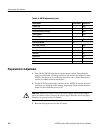
1. Turn off the AM700 using the rear power power switch. Disconnect the
power cord from the AC mains connector, and remove the cabinet from the
AM700. See the Remove and Replacement Procedures in the Maintenance
section for cabinet removal instructions.
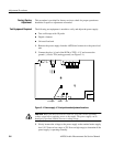
2. For the LCD flat panel display versions of the AM700, it may be necessary
to remove two shield from the Analog Acquisition board to make measure-
ments. Do this while the power is off.
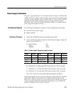
CAUTION. Dangerous voltages exist in the power supply. Observe the proper
safety precautions when servicing the power supply. Read the Servicing Safety
Summary for general safety precautions.
3. Reconnect the power cord to the AC mains.


