Theory of Operation
AM700 Audio Measurement Set Service Manual
3–63
string, U40. The data stream is applied to U11B (diagram 1) where it is read
back to the CPU board. The front-panel processor determines the buttons that
were pressed and initiates the appropriate action.
Picture Monitor Assembly (A10)
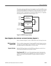
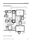
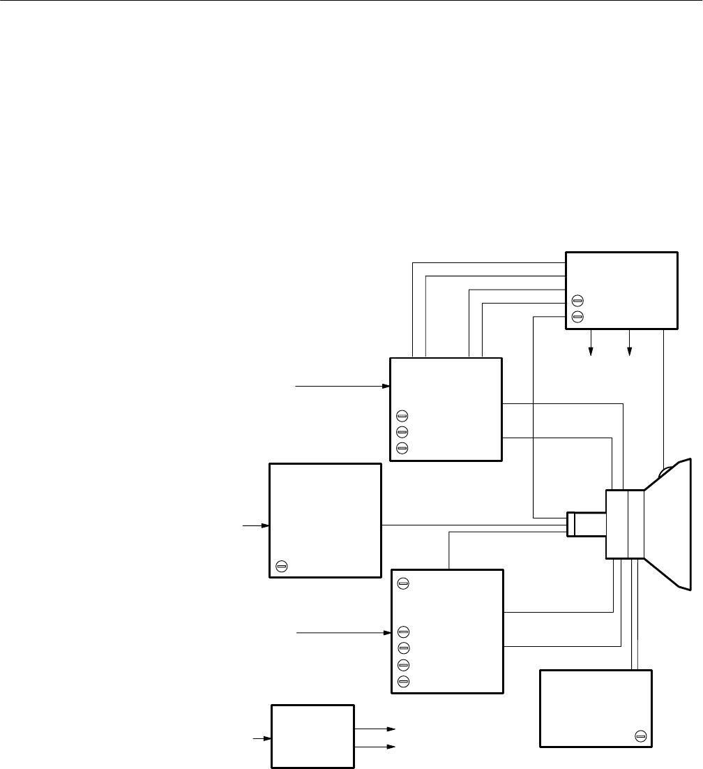
A simplified block diagram of the video monitor is shown in Figure 3–19. Refer
to the A10 schematic diagram for CRT display versions of the AM700.
High Voltage
Dynamic Focus
Focus
Horiz Phase
Horiz Hold
Width
White Level
+5V
+12V
Vert Centering
Vert Linearity
Vert Hold
Vert Size
+55V –110V
Video In
V Sync
Trace Rotation
Video Out
H Sync
+16.5V
Horizontal
Deflection
Video Amplifier
Vertical Deflection
Black Level
+12V
and
+5V
Supply
Figure 3–19: Picture monitor simplified block diagram


