


Theory of Operation
3–50
AM700 Audio Measurement Set Service Manual
The +5 V source to the NVRAM is monitored by U57. A backup battery is used
to maintain the stored memory of the NVRAM when the AM700 is powered off.
That battery is monitored for a low voltage condition so that a low battery
warning may be issued. When the battery is low, the NVBF interrupt is applied
to the Interrupt Encoder. That is a level 7 interrupt, and while the instrument is
running, it is masked to permit the CPU to maintain normal operation. At power
up, all the interrupt levels are enabled, so a low-battery interrupt will be seen and
the low-battery warning issued. The back-up battery must be replaced to prevent
loss of stored information in the NVRAM during power off.
A replacement battery may be installed using the pins on the CPU board placed
there for that purpose. After the replacement battery is installed, the lead to the
on board battery must be immediately cut to prevent it from drawing current
from the new battery.
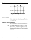
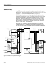
DRAM and Diagnostic Display (diagram 4)
Refer to schematic diagram 4 of the A6 CPU board for the following discussion.
The Dynamic RAM Controller (DRC), U33, provides most of the logic for
controlling the DRAM devices. The DRC requires initialization before it can
function normally. The DRC must be programmed during the first write cycle
that the CPU performs after reset.
An Error Detection Circuit detects parity error during every read access by the
host CPU. If an error is detected, the transfer error acknowledgement signal
(TEA) goes active and terminates a bus cycle, and the CPU may enter access
error exception. Both a DRAM parity check error and an illegal access will cause
TEA to be active. If any one of the BSR bits (bit 0 – bit 3) is asserted low, it
indicates a parity check error is detected. If illegal access occurred, BSR bit 16
will be asserted low.
After reset, BPR8 and BPR13 both are active low (‘0’).
BPR7 sets even parity or odd parity. After reset, even parity is set.
Table A-8 in Appendix A lists the address mapping accessed by the host CPU.
Table A-9 in Appendix A list the DMA mapping accessed by the DSP.
The diagnostic displays are used to troubleshoot CPU kernel problems when the
AM700 fails to boot. The segments of the diagnostic LED are turned on to
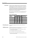
indicate the failed area as indicated in Table 3–2.
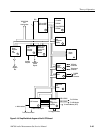
Battery Backup
Dynamic RAM Controller
Board Status Register
Diagnostic Displays