


Diagnostics
AM700 Audio Measurement Set Service Manual
6–21
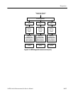
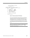
The low-level diagnostics consists of sets of tests that check the CPU (central
processing unit), the Display system, and the DSP (digital signal processor)
circuitry. The tests made in each of the circuits are shown in Tables 6–2, 6–3,
and 6–4. These tests are all run at power-on in V1.0/V1.01 firmware unless they
are intentionally bypassed by the user. They are skipped in V1.02 firmware
unless they are specifically selected by the user. Additionally, diagnostics tests
for the Digital Audio board, the Generator board, and the Floppy disk controller
are provided in V1.02 firmware. The tests shown in the tables are the main test
heading only. Each of the tests has additional subtest that are used by servicing
to further narrow the suspected failure error if a diagnostic failure occurs during
testing.
Usually, this power up running of diagnostics will be the only use of diagnostics
for the user. A service person can use the diagnostics to assist in determining if a
board or board set is faulty before doing a board swap to effect repairs to the
AM700. The normal use of the diagnostic tests is for factory testing prior to
shipment to the customer and repair testing of the boards returned in the board
exchange program.
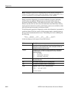
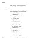
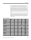
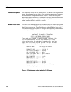
Table 6–2: CPU diagnostic (LL)
Test measmt unit min max result
Board Program Reg –Pass–
Board Status Reg –Pass–
Spurious Interrupts –Pass–
Bus Error Detect –Pass–
Dynamic RAM –Pass–
Parity Detect NA
Can’t test parity on 32-bit DRAM
NVRAM (read only)
Flash EEPROM –Pass–
Real Time Clock –Pass–
RTC Interrupt –Pass–
FP Ct’l ID Reg –Pass–
FP RAM: CPU side –Pass–
GPIB Controller –Pass–
GPIB Interrupt –Pass–
Serial Interrupt –Pass–
Timer Interrupt –Pass–
DUART 1 (serial) –Pass–
DUART 2 (kybd) –Pass–