


Theory of Operation
AM700 Audio Measurement Set Service Manual
3–77
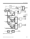
Over Voltage Indicator. If an over voltage condition exists, the /OVERVOLTS
signal from U9 is applied to both U18A as input to the shutdown logic circuit
and to an over voltage indicator circuit. The /OVERVOLTS signal is inverted by
U16A to fire SCR Q12. When that device fires, the over voltage indicator LED,
DS10 turns on to assist in troubleshooting an error condition in event of a power
supply over voltage problem. The SCR ensures that the indicator will remain on
until the power supply is completely turned off to remove the +14.4 housekeep-
ing supply voltage.
Overcurrent Comparator. The over current comparator, U17A, is referenced at
2.5 V from U9, pin 3. That reference is applied to the inverting input of U17A.
Under normal conditions, the outputs from the overcurrent sensing comparators
will not be active and VR3 will be conducting through CR43 and R133 to the
+14.4 supply. This will hold the noninverting input of U17A at 6.2 V and the
output of U17A will be high. The /OVERCURRENT signal is therefore high,
and the overcurrent LED will be off. Both the PS FAIL LED gate, U18C, and
Shutdown gate, U18B, will have a high signal on the over current input pins.
The over current signal input to U17A is formed by combining the outputs of the
individual power supply over current comparators. When an over current
condition on any power supply is detected, the common anode side of diodes
CR35 through CR38 or CR46 is pulled low, but the + input of U17A remains
higher than the – input until the voltage on C81 falls enough to cause the voltage
at the junction of CR43 and VR3 to fall below the reference input voltage on the
– input of U17A. The delay provided by the time constant of C81-R132 prevents
an over current condition from being generated by the current inrush when the
power supply first turns on.
The output of comparator U17A then goes down to ground level, and the over
current indicator, DS12, turns on. That low from U17A also causes a shutdown
(SD) to be generated from U18B to turn off the PWM, U1, and a high output
from U18C, the PS FAIL LED gate. The high from U18C biases on Q14 to
cause the PS FAIL LED signal to switch high.
When the PWM shuts down, the over current signal from the individual power
supplies will be removed, but the shut down signal must not be removed from
the PWM for a short period of time. This is done by the time it takes C81 to
change it charge state through R133.
While C81 changes charge level rapidly through R132 for an over current
condition, that path is not connected when the power supply shuts down and the
over current condition goes away. Through R133, the voltage across C81 rises
more slowly to a level that causes the comparator to again switch its output high.
That delay is how long the PWM remains off before it tries to restart. The
difference between the two times (run to off) is about 1:5 and the over current
indicator LED, DS12, will blink.