Diagnostics
6–48
AM700 Audio Measurement Set Service Manual
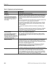
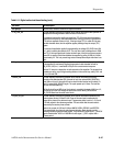
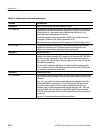
Table 6–11: Digital audio circuit board testing (cont.)
Test name Test description
Test group 3 Receiver tests, Generator tests which require the receiver.
3.11 ej_path_test This test internally connects the generator to the receiver and checks that a fixed level of
generated jitter is detected by the receiver’s eye/jitter loop. A large jitter level is checked
with jitter gain set to 1, and a smaller level is checked with jitter gain set to 8. The
operator measures the detected jitter at U124 pin 9.
This test checks operation of the low-pass filter, U126A/B and U127A/B, the switched
gain amplifier, U128B and U125, and the signal selector, U129.
It also exercises the jitter generator part of the generator pll, U103 and inductors L14/19.
3.11.1 js_lf_test This test internally connects the generator to the receiver and applies a self-calibrated
amplitude of low frequency jitter. The operator adjusts the center frequency of the
eye/jitter loop to set the varactor operating point for correct loop gain.
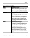
Test group 4 Reference input tests.
4.1 ref_lock This test internally connects the generator to the receiver and checks the locking
operation of the reference decoder, U87. It checks for lock, then pulses REF_RELOCK to
force U87 out of lock. It then waits 0.5 sec to check that the receiver has re-locked. If it
hasn’t, it pulses REF_RELOCK again. The cycle repeats up to three times. The test fails
after the third unsuccessful try.
U87 pins 9 and10 should be an AES signal. Lock status is encoded in the state of U87
pins 4, 5, and 6 which go to the 56k through the serial control chain. REF_RELOCK and
ER_CLEAR come from the serial control chain.
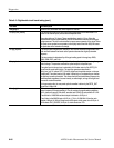
Test group 5 System data path tests.
5.1 cs_checksums This test internally connects the generator to the receiver and checks the data path all the
way to the DSP board by looking for the correct channel status checksum in the acquired
data record.
Test 1.7, stx_eye_pattern, has already checked operation of the data path from U102 to
the DSP board which is connected to J12. This test exercises the AES data path into
U102 for the first time. Inputs to U102 for the main aes path begin with “IN” on the
schematic. Inputs to U102 for the reference aes data path begin with “REF”. Each path
has bit clock (BCK), word clock (WCK), and data (DATA) signals. Bit clocks should be
3.072 MHz, word clocks should be 48 kHz, data should show some activity synchronized
to word clock.
Like test 1.7, this test is easily disturbed by ethernet conditions.


