Theory of Operation
AM700 Audio Measurement Set Service Manual
3–11
bit is included as the LSB bit of the data. That bit is set high or low depending
on the state of the output of the trigger circuitry.
Parallel Input
Serial Input
Serial Input
Transfer
Master Control
Transfer Clock
Start Flag
Data (8 Bits)
Data (24 Bits)
Control (6 Bits)
Eye Data In
Eye Data Start
Eye Data Clock
Left Data In
Left Data Start
Left Data End
Right Data In
Right Data Start
Right Data End
Bit Clock
Master Control (5 Bits)
Master Clock
from DSP
from
Eye Sample
from ADCs
or AES/EBU
Receiver
Serial Input
from ADCs
or AES/EBU
Receiver
Control
and
Global Signal Distribution
Left Data In
Left Data Start
Left Data End
Right Data In
Right Data Start
Right Data End
Bit Clock
Control (10 Bits)
Control (10 Bits)
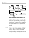
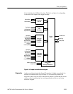
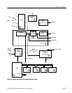
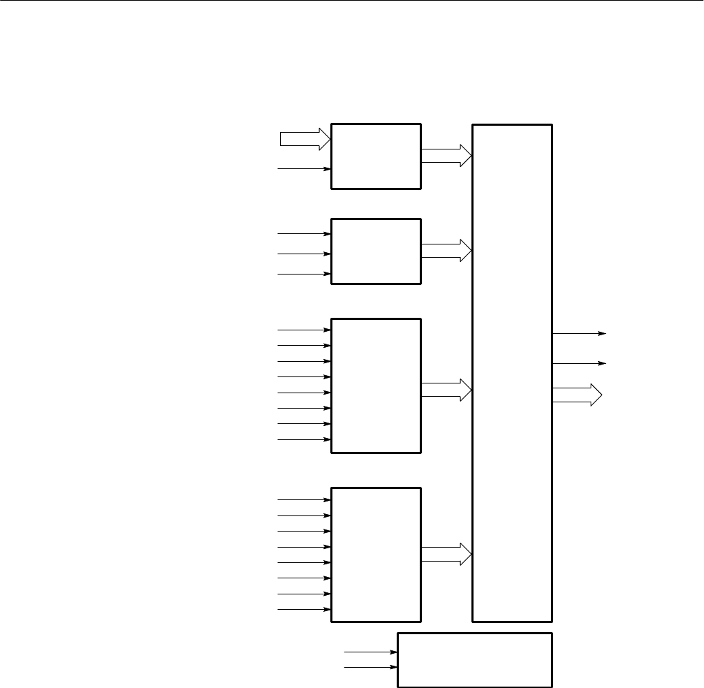
Figure 3–4: Sample transmitter block diagram
As the normal data through the Sample Transmitter is highly uncorrelated, it is
difficult to troubleshoot the logic circuitry. To overcome this problem, the
diagnostic routine at power up uses known test patterns to check that the various
sections of the formatting logic are working properly and bits are not being
missed or dropped.
Diagnostics


