Theory of Operation
AM700 Audio Measurement Set Service Manual
3–17
2
1
RAM
12.288 MHz
Host
Port
3
10
10
1
1
1
1
9
9
8
Oscillator
Serial Control
ONCE
DSP
Control
SSI Interface
and
Sample
Transmitter
Reset
Data
Control
(RST)
(STX_CE)
(PHASE_CE)
Address
(ENCJIT_CE)
(COUNT_CE)
Data
Address
SSI
To/From
RAM_CE
Host Reset
A(0 –15)
D(0 – 23)
(DSPRST)
Generator Clock
Address
Decoder
DSPCLK
Timing
Generator
Control
Functions
DSP Port
Control
Serial
Control
Registers
Serial Control
of Frequency Synthesizer
Host Cable
to CPU Board
Decimal Point is
Power ON Indicator
Port
Address
D(0 – 23)
A(0 –15)
Generator Data
and ADC
Sample Transmitter
Phase Shift Control
AES Encoder Control
Jitter Control
Frequency/Phase Counter
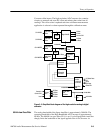
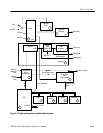
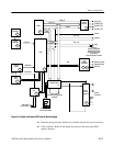
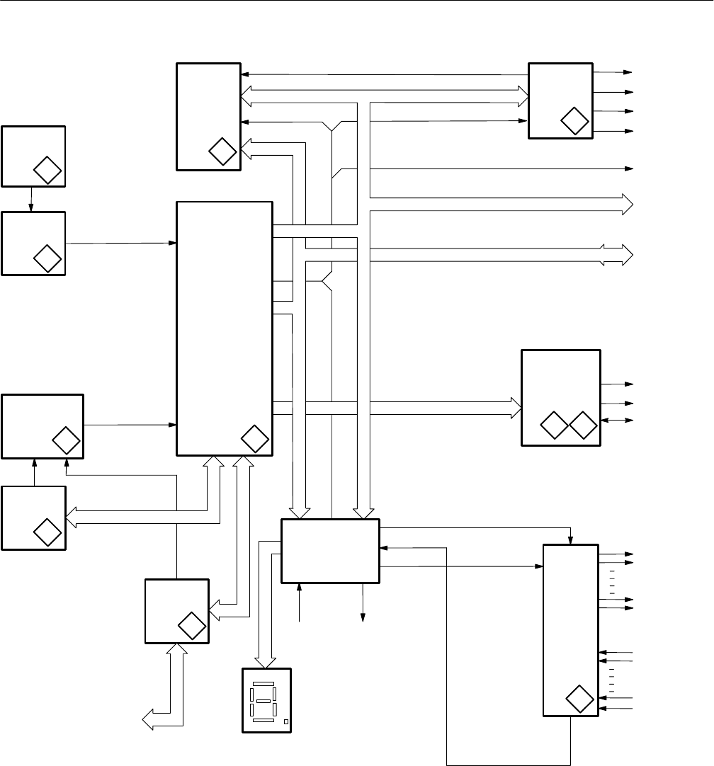
Figure 3–6: Digital audio board DSP section block diagram
H Interface jitter generation. Works only with the jittered sine-wave waveform.
H Cable simulator. Rolls off the digital waveform to the front panel XLR
output connector.


