Theory of Operation
AM700 Audio Measurement Set Service Manual
3–67
Power Supply Board (A11)
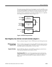
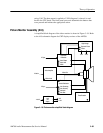
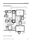
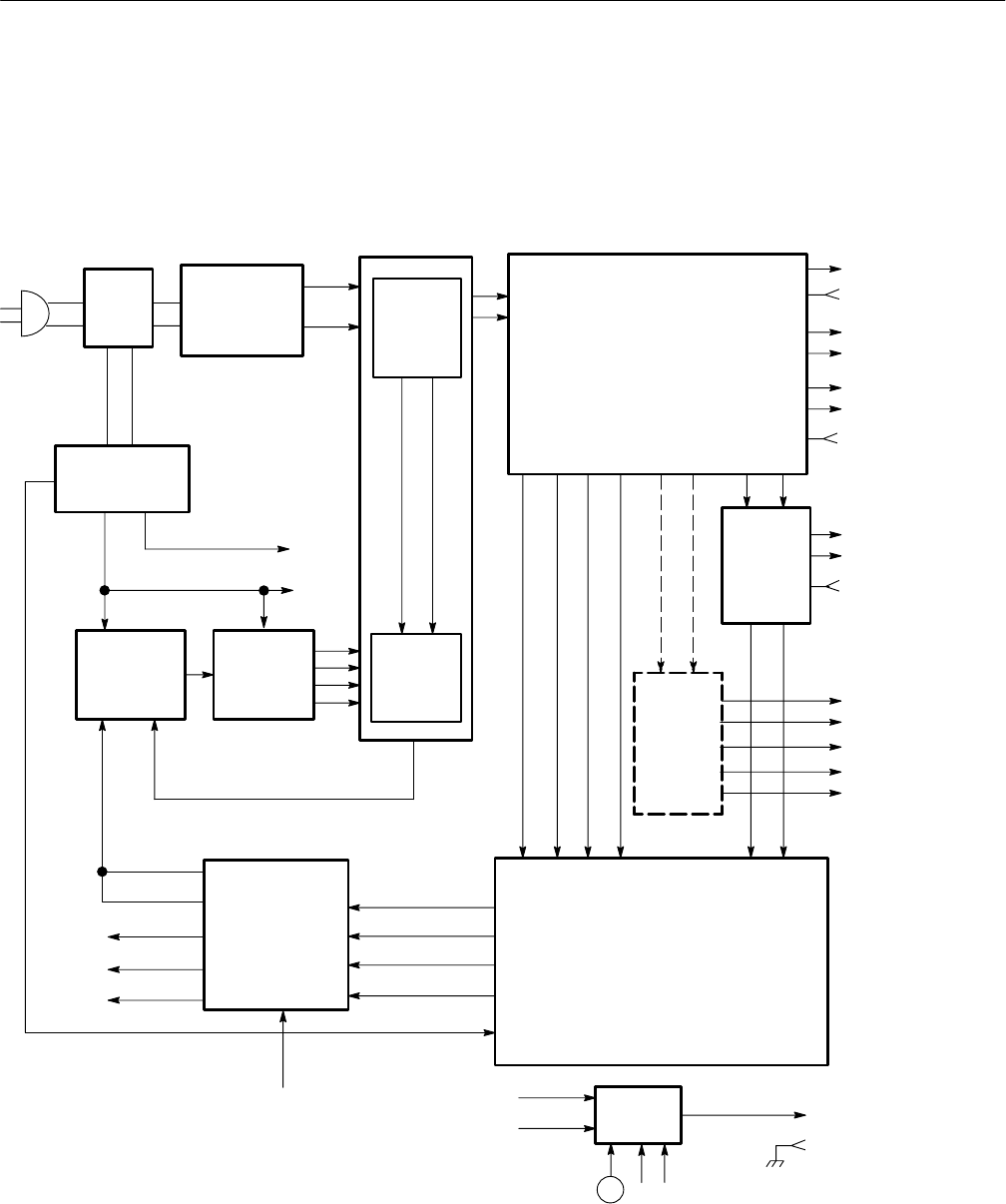
A block diagram of the power supply is shown in Figure 3–20. Refer to the
illustration for the following functional block description of the power supply
circuitry.
_t
Line
Voltage
Switch
Input
Inverter
Output
15V
Floating
Primary
Power
Pulse Width
Alarm
Alarm Sensing
Fan
Housekeeping
Supply
Power
Rectifier
Switching
Circuit
Rectifiers
Regulators
Supplies
(LCD
Flat Panel
Display)
Current
Sensing
Modulator
Switch
Driver
Logic
Drive
+5V
+5V Ret
+22V
–22V
+16.5V
–16.5V
+16.5V Ret
+15V
–15V
15V Ret
+14.4V
+15V
–15V
+5V
–22V
–14.4V
OVSD
SD
+14.4V
PS Fail LED
Overtemp LED
Overcurrent
/Overvolts
/Undervolts
/Power Fail
Housekeeping
/Undervolts
+12V
Fan+
Fan Ret
T1 T2
+22V
–22V
–16.5V
+16.5V
Line Sense
Power Off
+Vp
–Vp
SD
Current Sense
+22VI
–22VI
+5VI
+16.5VI
+15VI
–15VI
+22V
Figure 3–20: Power supply block diagram


