Adjustment Procedures
AM700 Audio Measurement Set Service Manual
5–15
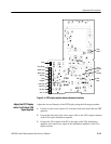
Horiz
Width
Vert Lin
Vert Size
Vert Hold
Horiz Hold
Trace
Rotation
Focus
Horiz Phase
White Level
Black Level
Vert Pos
Vert
Retrace
Horiz
Retrace
VGA
Input
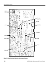
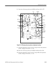
Figure 5–4: CRT display monitor board adjustment locations
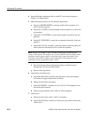
Adjust the size and linearity of the CRT display using the following procedure.
1. Connect a video source cable to J2 on monitor board and install the test CRT
graticule.
2. Connect the other end of the video source cable to the VGA output connector
of the VGA signal distribution amplifier.
3. Connect the VGA output of the PC to the input of the VGA distribution
amplifier, and connect one output of the distribution amplifier to the VGA
display monitor.
Adjust the CRT Display
with a Test Pattern VGA
Signal Applied


