Adjustment Procedures
AM700 Audio Measurement Set Service Manual
5–25
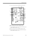
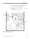
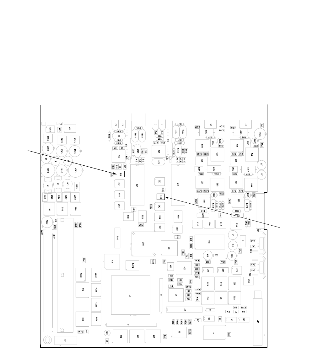
3. Adjust the A DAC GAIN, R24, of the Analog Generator for an amplitude of
1.000V ± 0.0001V. See Figure 5–6 for the adjustment locations.
4. Move the XLR connector from Ch A OUT to Ch B OUT.
5. Adjust the B DAC GAIN, R18, of the Analog Generator for an amplitude of
1.000V ± 0.0001V.
6. Disconnect the test equipment from the AM700.
B DAC Gain
(Right)
B DAC Gain
(Right)
Figure 5–6: Generator board adjustment locations


