Removal and Replacement Procedures
AM700 Audio Measurement Set Service Manual
6–79
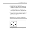
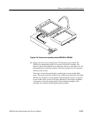
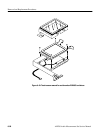
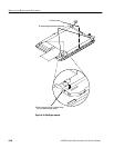
Figure 6–39: Touch screen assembly removal B020253 to B020692
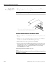
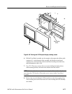
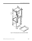
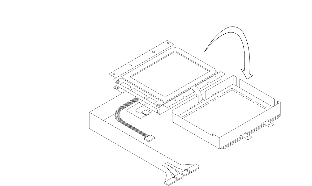
11. Remove the four screws holding the LCD flat panel to rear shield. The
AM700 was manufacuted with two versions of the LCD assembly. See
Figure 6–40 for the exploded view of the new version or see Figure 6–41 for
the exploded view previous assembly. Note that a ground wire is connected
with one of the screws.
The newer version flat panel display assembly has several notable differ-
ences. The touch screen lead comes out at a different location (the side rather
than the top) and there are two separate LCD backlight inverters as opposed
to one for the earlier version. The major difference is the display brightness
of the newer version flat panel display. The mechanical changes to the
assembly also simplify assembling the display module.


