


Diagnostics
6–42
AM700 Audio Measurement Set Service Manual
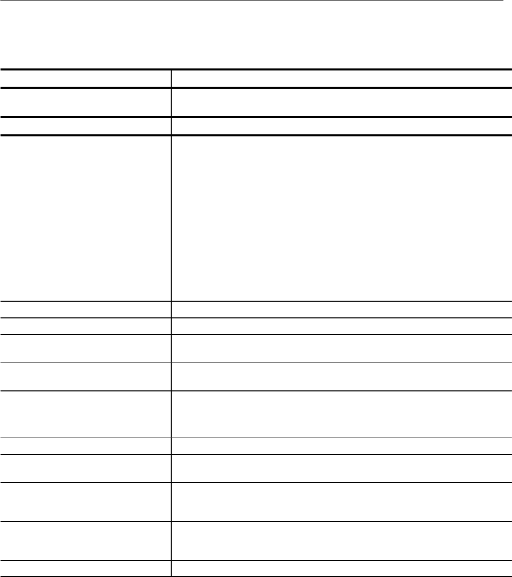
Table 6–11: Digital audio circuit board testing
Test name Test description
Test Group 0
Check power supplies (three terminal regulator outputs) and adjust 12.288 MHz crystal
oscillator Y1.
Test Group 1 These are low level tests, mostly read and write tests of all writeable registers.
1.1 host_com
Requires functioning dsp kernel and host
port
Downloads tap 6.56k.
Dsp kernel includes: +5 V through fuse F3
DSPCLK 3.072 MHz from U115 pin 19
U115 pin 13 12.288 MHz from Y1
(DSPRST) J2 pin 11 high from U140 pin 18
U140 pin 27, pin 42, and 43 or’ed resets all high
U5 Address Decoder pal, U98 SIMM
Most of the resistors and capacitors
Host port includes: U99, U100, U144. Host cable
1.2 board_id Reads board ID from pal U117. Board ID may change with future board versions.
1.4 bbang_rw Writes then reads the trigger bit in U117
1.5 flags_rw Reads the flag bits which are pulled low if XLR and rear panel cables are plugged in.
Prompts operator to remove and attach cables.
1.6 stx_rw Writes then reads all r/w registers in the sample transmitter U101 with several bit
patterns.
1.7 stx_eye_pattern Puts eye sampler U130 in test mode to generate a fixed data pattern which is connected
serially to Sample Transmitter U101.
The DSP board receives the data, and it is checked for the correct pattern.
1.8 pshift_r/w Writes then reads the phase shift register in U104 with several bit patterns.
1.9 counter_rw Writes then reads the two bit control register in Counter U139 and U140 with a few bit
patterns.
1.10 serial_chain Shifts a 32 bit pattern through the serial control/status chain and checks that the pattern
doesn’t change. Requires U117 for control. U95, U96, U97, U142, U141, U93, and U94
form the chain.
1.11 dsp_channel Sends a sequence of bit patterns from the 56k dsp, through the sample transmitter, out
the sample cable to the DSP board. Checks that received bits are same as sent bits.
Sample transmitter U101 is put into dsp mode by STX/DSP line from U141 pin 2.
1.12 led_w Writes an dynamic pattern to the LED display. Requires U116, R299, DS2.