Removal and Replacement Procedures
AM700 Audio Measurement Set Service Manual
6–57
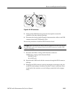
The catches are also extracting levers, and they disengage the connector from the
pins in the connector housing. To reconnect, align the connector with the pins in
the housing and press firmly to seat the connector. The catches should snap into
place when the connector is fully inserted. Press the catches together to ensure
that they are completely engaged over the top of the connector.
Power cables are heavier gauge ribbon cable and use large in-line square-pin
connectors to handle the current required to power the assemblies.
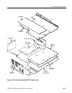
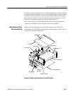
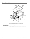
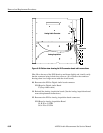
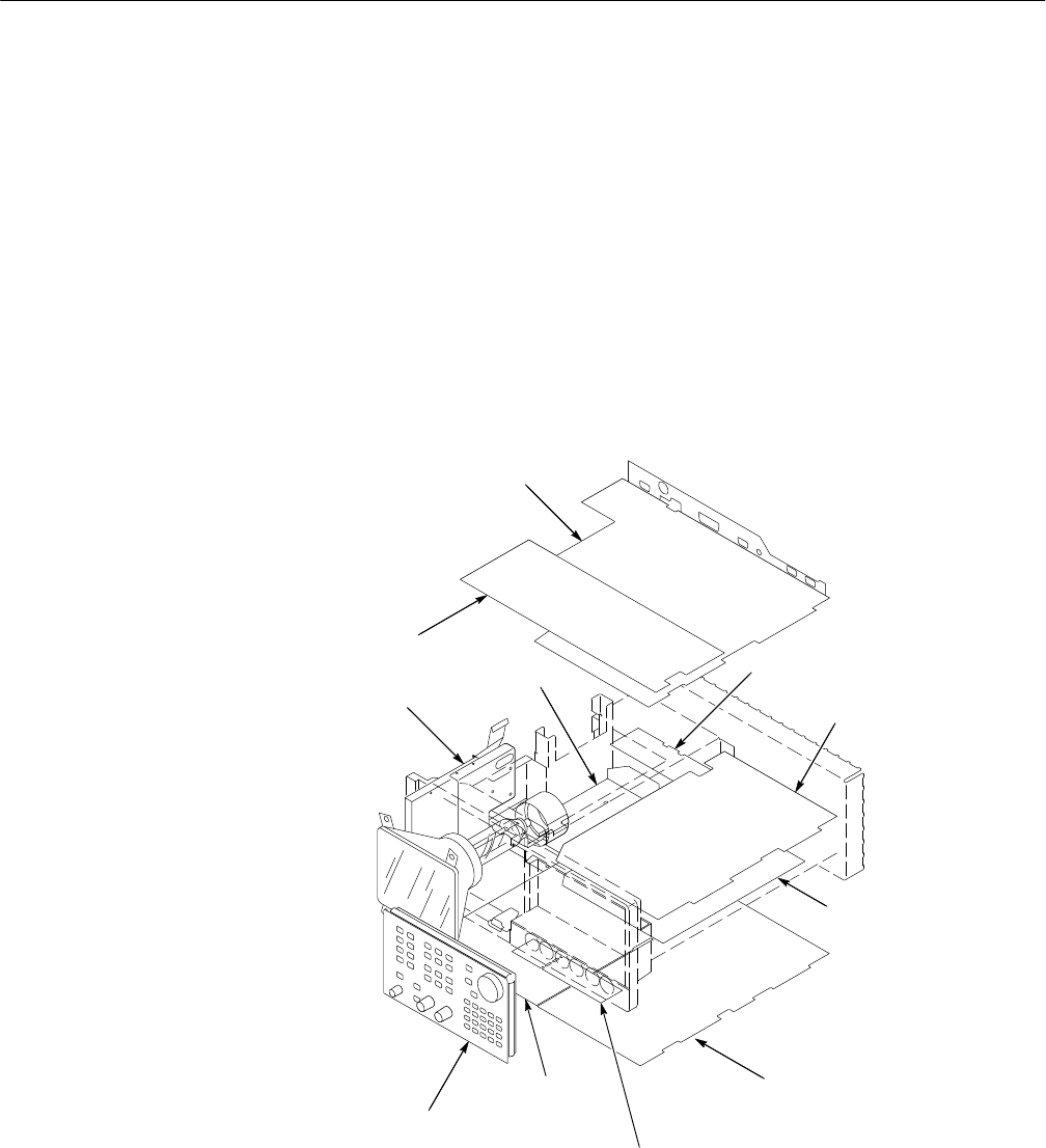
Figure 6–22 shows the locations of the major modules in the CRT display
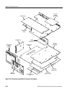
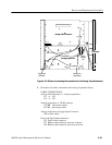
measurement set. The LCD flat panel display measurement set modules are very
similar, and are shown in Figure 6–23.
A7 DSP
A6 Main/CPU
A12 Disk drive
A4 Rear panel
A3 Digital audio
A11 Power supply
A1 Analog acquisition
A2 XLR Connector
A5 Audio
generator
A9 Front panel
A10 Monitor
Figure 6–22: Major module locations for the CRT display
Major Modules (Circuit
Board Assemblies)


