Maintainence
AM700 Audio Measurement Set Service Manual
6–11
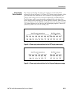
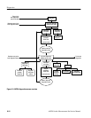
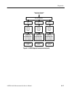
The voltages produced by the main power supply are monitored by LED
indicators as shown in Figure 6–2 or Figure 6–3. During normal operation all the
green LED indicators should be on. Error conditions (over temperature, over
voltage, under voltage, and over current) are indicated by red LED indicators.
These indicators may be seen through the ventilation holes in the side of the
power supply housing when the cover of the AM700 is removed. When only the
rear power switch is on, the AM700 is in standby mode; and only the +14.4 and
–14.4 green indicators are on (these are the housekeeping supplies). The red UV
(undervolts) LED is also on in the standby state.
Green LED normal voltage indicators Red LED error indication
DS7
+22
DS4
+16.5
DS3
+15
DS8
+14.4
DS5
+5
DS2
-14.4
DS6
-15
DS13
-22
DS9
OT
DS10
OV
DS11
UV
DS12
OI
Figure 6–2: Power supply status indicators for the CRT display power supply
DS4
+16.5
DS3
+15
DS8
+14.4
DS5
+5
DS2
-14.4
DS6
-15
DS9
OT
DS10
OV
DS11
UV
DS12
OI
Green LED normal voltage indicators Red LED error indication
Figure 6–3: Power supply status indicators for the flat panel display power supply
Power Supply
Status Indicators


