


Theory of Operation
3–40
AM700 Audio Measurement Set Service Manual
The current output of the DACs is converted to a voltage level by the Current to
Voltage (I-to-E) converter circuits, U19B on the left channel, and U13B on the
right channel. The components on the minus inputs of the I-to-E converters filter
conversion glitches from the DACs. The output voltage of these devices is
applied to the DAC Low-Pass Filter circuitry for smoothing.
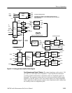
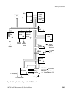
DAC Low-Pass Filters (diagram 4)
Refer to schematic diagram 4 of the A5 analog generator circuit board for the
following circuit description.
The low-pass filter for the A and B DACs (left and right) have two filter paths: a
20 kHz low-pass filter path and a 80 kHz low-pass filter path. These two paths
are in the circuit all the time. The path selection is made at the input to the
Gain/Attenuator circuitry (diagram 6).
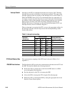
The 20 kHz low-pass filter is used for the High Resolution mode generators. The
generator output is up to 20 kHz. For high resolution signals, the filter is a
5-pole, linear-phase filter circuit. This means that the active devices serve to
preserve the phase of the signal through the filter to 20 kHz. Output from the
Low Pass Filter is applied to the Tunable Bandpass Filters (diagram 5).
Filtering for the High Bandwidth signal, which goes up to 80 kHz, is done by a
hybrid, 11-pole elliptical filter. This filter introduces some DC offset, so the
output is AC coupled to the next stage to eliminate any DC components from the
filtered signal. Output from the 80 kHz low-pass filters is applied directly to the
data selector in the Gain/Attenuator circuitry (diagram 6).
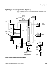
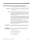
Tunable Bandpass Filters (diagram 5)
Refer to schematic diagram 5 of the A5 analog generator circuit board for the
following circuit description.
There are two paths for the left and right High Resolution generator signals
relative to the Tunable Bandpass Filters. These are the bypass path and the path
through the tunable filters. The choice is user selectable in the generator
Advanced Analog Controls and is called “Low Distortion” mode when the
bandpass filter is inserted. Either high resolution generator signal or both may be
routed through the tunable filters.
Current to Voltage
Converters
Filter Paths
20 kHz Low Pass Filter
80 kHz Low Pass Filter
Filter Paths