


Theory of Operation
AM700 Audio Measurement Set Service Manual
3–75
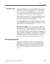
When the voltage is coming up, it is also important that the memory devices in
the instrument are not written to randomly. The Power Reset Comparator has an
RC timing circuit on its non-inverting input that prevents the /PWR RESET
from going high for a period of time after the undervoltage condition is removed
(see Figure 3–15). The delay permits the power supply voltage to stabilize before
the processor is permitted to start operating.
Each of the voltage outputs has a current sensing resistor of low ohmic value to
provide overcurrent information to the Alarm Sensing circuitry. In the +5 V
regulator, that resistor is R39. The total current to the +5 V load passes through
R39. The +5 VI (current sense) level is compared to the +5 V (output) level by
the +5 V overcurrent comparator, U11A, in the Alarm Sensing circuit. The other
supplies have similar sensing resistors in their load current paths. The current
sense voltage of each supply is compared against its output voltage to the load
by individual comparators in the Alarm Sensing circuit. A marked difference
between the two levels causes the associated comparator output to switch low to
indicate an overcurrent condition.
Overcurrent Sense Comparators. Individual comparators for each of the power
supply outputs monitor both the output voltage to the load and the voltage
developed across a current sense resistor in each load path. If the difference
between the two levels increases beyond design levels, the associated comparator
switches states from a normal high to low. The low forward biases a diode in the
OR’ed output line of the comparators to pass the overcurrent condition signal to
the Alarm Logic circuit to cause the power supply to shutdown.
All the comparator circuits are the same with the exception of the +5 V
comparator. The exceptions to that circuit will be discussed after the general
description for the remaining comparators. The +22 V circuit is used as the
example. In that circuit, U12B is the comparator. On the + (non-inverting) input,
a voltage divider circuit formed by R93 and R96, has a divide ratio that produces
approximately 8.32 V at pin 9 between the +22 V output and the –14.4 V
housekeeping supply. (Notice that in the negative voltage supplies, the +14.4 V
housekeeping supply is the reference.)
On the – (inverting) input, a voltage divider formed by R94 and R95 has a divide
ratio that produces approximately 8.07 V at pin 10 between the +22 VI current
sense voltage and the –14.4 V housekeeping supply. If the current in the +22 V
load increases to the point that the +22 VI level rises to the point that the voltage
on pin 10 exceeds the voltage on pin 9 of U12B, the comparator changes states,
and the output on pin 7 goes to ground level. That ground level signal forward
biases CR38 and pulls the common diode-OR’ed anode line to ground. That line
is connected to the Overcurrent Comparator U17A.
In the +5 VI comparator, the voltage swing across the current sense resistor is
very small. To improve the sensitivity of the comparator, VR1 holds a voltage
drop of 5.6 V across a divider formed by R78 and R80. In the anode circuit of
Overcurrent Sensing