


Theory of Operation
AM700 Audio Measurement Set Service Manual
3–65
Spot Eliminator. An additional circuit formed by CR11, CR12, C44, and R66,
produces an extra bias to the control grid to positively cut off beam current
during turn on and turn off of the AM700. These pulses at turn on and turn off
are transitory as the power supplies turn on and off. As the +55 V and –110 V
voltage supplies come up, the voltage at the junction of C44 and R66 spikes
negative to bias on CR12 and add a negative biasing pulse to the control grid. At
the voltages stabilize, CR12 become reversed biased, and the extra circuitry is
switched out of the control grid circuit. At turn off, the junction of C44 and R66
is setting at +55 V. Diode CR11 becomes biased on as the +55 V supply falls,
and this negative pulse also biases on CR12 to pass the extra biasing pulse to the
control grid.
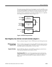
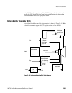
The horizontal deflection circuit provides the drive current to the deflection
yoke. A PLL (phase-locked loop) circuit, U1, produces the horizontal deflection
signal. The frequency of the loop is synchronized to the incoming H Sync signal
after setting the correct frequency with the Horiz Hold control, R20. Further
amplification of the signal is done by Q4 and Q5 to provide the necessary levels
to drive the horizontal deflection yoke. The other side of the horizontal deflec-
tion yoke is AC referenced to ground through L3 (a saturable reactor), L4 (the
horizontal WIDTH control), and C17. Diode CR9 catches negative overshoots of
the horizontal deflection signal.
A circuit from the output of Q5 to the SAW IN input of U1, pin 4, provides
feedback to the PLL circuit. The Horiz Phase control, R15, in the feedback path,
is adjustable to fine position the active picture area within the raster scanned
width.
+20 V Boost Supply. A circuit composed of CR2, CR3, C18, C19, C20, R31, and
a winding (pin7 to pin3) of T2 (in the high voltage supply) boosts the +12 V
source to +20 V to supply the collector voltage for Q4. At the collector of Q5,
the horizontal retrace pulses have a amplitude of approximately 320 V. The
nearly constant voltage level between the retrace pulses produces a ramp of
current to the horizontal deflection yoke.
The high voltage supply provides the crt anode voltage, the focus voltage, and
the +55 V and –110 V sources. Drive to T2, the high voltage transformer, is
provided through a set of taps on the multitap primary winding.
The crt anode voltage and the –110 V supply are taken from separate secondary
windings in the transformer. A diode internal to the transformer module rectifies
the high voltage for the crt. That voltage is also referenced to ground internally
in the transformer module. The –110 V winding is rectified by CR7 and
capacitively filtered by C24.
Horizontal Deflection
High Voltage