Removal and Replacement Procedures
AM700 Audio Measurement Set Service Manual
6–61
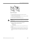
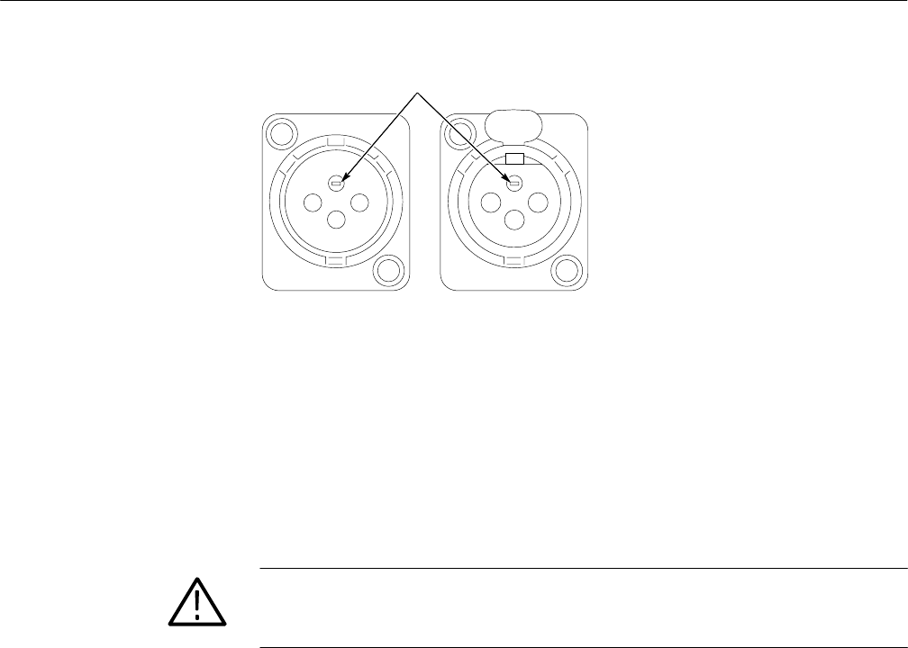
Slot
PUSH
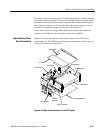
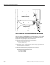
Figure 6–25: XLR connectors
5. Gently pull the XLR board away from the front panel to extract the
connectors from the connector housings.
6. Disconnect the Analog Audio Generator interconnection cables to the XLR
connector board at J8 CH B and J9 CH A.
Reverse the procedure to install the XLR Connector board.
CAUTION. When reinstalling the XLR Connector board do not allow the wires to
the STBY/ON switch to be captured between the XLR connectors and the XLR
connector housings.
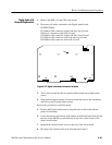
7. Reconnect the XLR to Analog Audio Generator connectors.
XLR Board to Analog Audio Generator Board
J9 B OUT to J8
J8 A OUT to J9
8. Reposition the XLR board with the connectors through the XLR connector
housings.
9. Reengage the XLR connector locks by inserting the screwdriver in the slot
on the lock and rotating it clockwise (less than 1/4 turn is sufficient). Press
on the back of the connector you are locking to permit the lock to engage
easily.


