


Appendix A: Memory and Register Mapping
AM700 Audio Measurement Set Service Manual
A-5
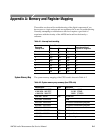
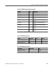
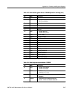
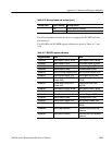
Table A-9: DRAM address map (96002 DMA access)
Address(hex) Size BSR6 BSR5 BSR4
CC00 0000 – CC0F FFFF 4 MB 0 0 0
CC00 0000 – CC1F FFFF 8 MB 0 1 1
CC00 0000 – CCFF FFFF 16 MB 0 1 0
1
BSR6 = Board Status Register bit 6
BSR5 = Board Status Register bit 5
BSR4 = Board Status Register bit 4
If BSR6=BSR5=BSR4=1, it means no DRAM installed.
BSR address = 1200 0000
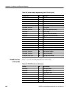
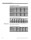
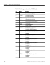
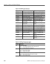
The diagnostic displays are used to troubleshoot CPU kernel problems when the
AM700 fails to boot. The segments of the diagnostic LED are turned on to
indicate the failed area as indicated in Table A-10.
Table A-10: Diagnostic LED definitions
LED Description
0 reserved
1 reserved
2 on : Flash EPROM (bank 0) not found
3 on : Flash EPROM (bank 1) not found
4 on : Flash EPROM (bank 2) not found
5 on : DRAM not found
6 on : battery supply failure
7 on : hardware reset active
NOTE. LED Display Register (LDR) (1400 0010), byte write transfer is required.
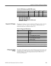
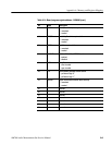
The settings of the segments of dip switch S3 define the operational mode of the
operating system. Certain settings are used for troubleshooting only and are not
normally changed to any other settings than those listed in Table A-11 for
Normal System Operation.
Diagnostic LED Displays
S3 Diagnostic Switch
Settings