


Theory of Operation
AM700 Audio Measurement Set Service Manual
3–49
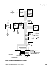
Memory Controller, EPROM, FEPROM, and NVRAM (diagram 3)
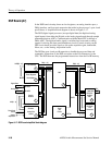
Refer to schematic diagram 3 of the A6 CPU board for the following discussion.
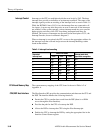
The EPROM is a 32-bit wide device, and the maximum memory allowed on
board is 1 Mbyte. This memory is where the system boot-up code is loaded. It is
read only memory, and data transfer type can be byte, word, or long word. The
EPROM Address space for the possible memory sizes is shown in Table A-4 in
Appendix A.
The NVRAM consists of a 32-bit wide static memory divided into two banks.
Each bank consists of 512 Kbytes of memory. The maximum memory residing
on board is 1 Mbyte. The memory interface allows either normal mode or burst
mode access. The data transfer type can be byte, word, or long word.
The power to the NVRAM is backed up by the on-board battery, so memory
content is protected against power failure and saved during power off. The
memory interface monitors the battery supply voltage. In the event the battery
voltage falls below the specified value for safe backup, a NMI interrupt in
generated to interrupt the CPU.
After power up or any CPU reset, the NVRAM devices are write protected. Bit 0
of the Board Program Register must be set to a zero before storing data to
NVRAM. If not, a write to these locations will not be stored. Table A-5 in
Appendix A gives the NVRAM address mapping access by the CPU.
There are two SIMM (single-inline memory module) sockets on the CPU board
for Flash EPROM. The maximum memory permitted is 16 Mbytes. Data transfer
type for read access to the FEPROM can be byte, word, or long word. The
FEPROM memory is write protected. Memory mapping of the Flash EPROM
accessed by the CPU is given in Table A-6 of Appendix A. The amount of flash
memory available is identified by as shown in Table A-7 of Appendix A.
Writes to Flash EPROM. When the Flash EPROM is written to, it is set up for
long word writes only. The steps that occur for a write (during programming of
the FEPROM only) are the following:
BPR bit 1 is set to 0
The FEPROM is ready to program when BPR bit 13 becomes set to 1.
If these bits are not set correctly, a write to the FEPROM will have no effect.
EPROM
NVRAM
Flash EPROM (FEPROM)