


Theory of Operation
AM700 Audio Measurement Set Service Manual
3–69
±15 V Regulators. The + and –15 V regulators are similar in operation. Each
regulator is a combined operational amplifier and FET current pass element with
a feedback loop to the operational amplifier from the output voltage.
Alarm Sensing. The Alarm Sensing circuitry looks at the various supply voltages
to check for undervoltage, overvoltage, overcurrent, and power fail conditions.
The status of these conditions are the signals fed to the Alarm Logic circuitry.
Alarm Logic. Each of the Alarm Sensing outputs is monitored by the Alarm Logic
circuitry. That circuitry also monitors the temperature sense signals. Depending
on the state of the sense signals, the Alarm Logic circuitry can issue a shutdown
signal (SD) to the Pulse Width Modulator to stop the power supply from
operating. The Alarm Logic circuitry also drives the Over Temp LED and PS
Fail LED front-panel indicators as feedback to the user of the existing problem.
Fan Drive. A separate Fan Drive circuit provides a temperature related drive
voltage to the Fan. As the temperature rises, the fan is driven faster to compen-
sate for the rise. The temperature sensing element for the voltage control is
mounted on the 5 V power supply heat sink.
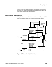
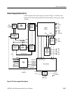
Floating Power Supply. In CRT display instruments, these supplies are located on
the Generator board (A5). In LCD flat panel display instruments, the floating
supplies are part of the power supply board.
The floating power supply provides the isolated voltages to power the analog
audio generator. This isolation permits the generator outputs to float with respect
to chassis ground. The +22 V and –22 V outputs of the power supply power a set
of 3-terminal regulators that provide the +15 V, +5 V, and –15 V to the Generator
board. Those voltages, along with the +22 V and –22 V voltages and the floating
return line are connected to the Generator board through J12 on the power supply
board.