9–7
AM700 Audio Measurement Set Service Manual
Bypass
5,9
4,16
U35
Channel 1
Channel 2
6,8
1,3
10 (15)
Select
Notch
CH A
Logic 1
13 Bit
CH B
CH A (CH B)
Inserts Notch
Address
Line
Bandswitch is
U42 (U34)
U37 – 42 (U29 – 34)
Programmable Notch Filter
Two Bands
750–20,200 Hz in 5 Hz Steps
20–750 Hz in 0.183 Hz Steps
Q=2.7 Depth > 20dB
2.00 K
20 K
–
+
U39B (U31B)
10
Selects
Av = 20 dB
m
F
TP12 (TP11)
Notch to
High Res
and/or
High BW
U43 (U36)
To High Res
Logic 1 Inserts Notch
A/D Circuitry
To High BW
A/D Circuitry
Logic 0 = No Notch (Bypass)
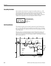
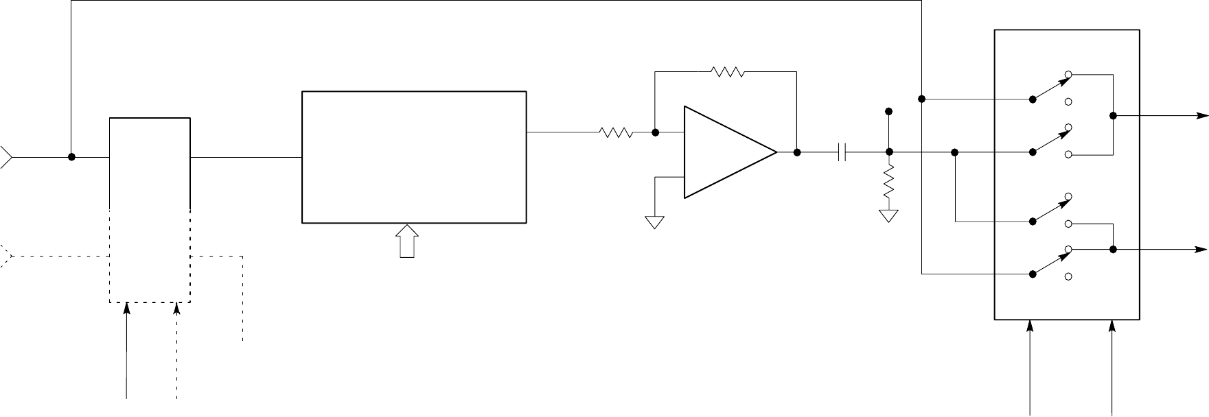
Figure 9–3: Analog Acquisition input section CH A notch filter


