


Theory of Operation
3–54
AM700 Audio Measurement Set Service Manual
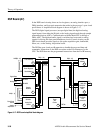
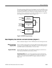
VRAMDAC and Floppy Drive Interface (diagram 9)
Refer to schematic diagram 9 of the A6 CPU board for the following discussion.
There are two identical Video RAM/DAC devices, U37 and U15. One, U37,
produces the monochrome drive to the internal display monitor. The second,
U15, provides RGB output to drive an external VGA monitor. Pixel data bytes
from the Video ASIC are converted to analog at the IOR, IOG, and IOB outputs
of the Video RAM/DAC. For CRT display systems, the Red and Blue outputs of
U37 are terminated, and only the Green output is used to drive the monochrome
display. That signal is sent to the Display Monitor board along with the
Horizontal and Vertical Sync signals through connector J2. Test points (TP13,
TP14, and TP15) are provided for checking these signals. In U15, all three color
outputs plus the Horizontal and Vertical Sync signals are connected through EMI
filters to the rear-panel VGA connector, J3. A single test point (TP16) is
provided for checking the Green drive signal.
The Video RAM/DAC provides the RGB and sync signals to the LDC Driver for
AM700 Audio Measurement Sets that have the LCD color flat panel display
system.
CRT Display Brightness. The brightness of the internal display monitor and the
external display monitor are controlled separately through the current references
to the Video RAM/DAC devices. A digital to analog converter, U28, get
brightness information from the CPU data bus. One output of U28 provides drive
to the reference current source of U37 through U4A, and the other output
provides drive to the reference current source of U15 through U4B. The internal
display monitor brightness is adjustable from the front panel of the AM700. A
suitable level is set for the external VGA monitor output, and the controls of the
external monitor may be used to set it for the desired viewing brightness.
LCD Display Brightness. When the LCD flat panel display is installed, the
brightness is a function of the backlight intensity. The display brightness is
adjustable from the front panel control as is the CRT brightness, but the
brightness level signal line is applied to the backlight inverter power control
circuit on the LCD driver board. The control circuit has a brightness level
adjustment that sets the extinguish level (no visible display) of the LCD display.
The interface between the I/O processor, U110 (diagram 7), and the floppy drive
is provided by U105, a single-chip controller. The controller handles the data
transfers to and from a floppy disk using DMA after requesting access to
memory from the I/O Processor. This allows the I/O Processor to continue its
other tasks without further interruption for the data transfer.
Video RAM/DAC
Floppy Drive Controller