


Theory of Operation
AM700 Audio Measurement Set Service Manual
3–13
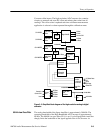
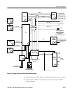
loaded. That path permits a diagnostic routine to write serial data on the
CONTROLAIN data line and read it back to determine if the control path is
functioning correctly. The CAL BUSY signal tells the DSP that a calibration is
in progress.
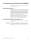
A TTL trigger signal input is applied to a Schmitt trigger device, U111D. The
output of the Schmitt trigger is buffered by U121C. When U121C is enabled, a
trigger event is output to the Sample Transmitter where it is included as the LSB
bit of the digitized audio data.
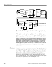
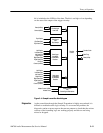
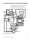
Over/Under Range Board (A1A7)
This assembly is a small circuit board that is physically attached to the A1A1
Analog Acquisition board. Its circuitry is composed of comparators used to
determine if the applied analog input signal is overrange (signal too big for
application to the A/D converter) or underrange (signal amplitude that is small
enough that a higher gain step or less attenuation should be used to provide a
better dynamic range signal to the A/D converter).
The fixed input of the comparators is supplied through a voltage divider circuit.
One output of the divider is the voltage that is the overrange level and the other
is the underrange level. The analog signal from the A and B Input Attenuators
(after the gain and attenuation stages) is applied to the comparators. The output
of each comparator is applied to a latch circuit that holds the state of the
comparison. A (CLRORANGE) (clear overrange) signal is applied to the latches
to clear the states in preparation for a new comparison.
Those states are applied to a data selector, U5, that is checked to determine if
over- or under-range conditions exist. If either condition is found, the control
signals to the Channel A or Channel B Input Attenuator boards are modified to
change the gain or attenuation as needed to adjust the input signal level to the
A/D converters. The CHA/(CHB) SEL signal switches the data selector between
the Channel A and Channel B range states so each channel can be checked
separately.
XLR Connector Board (A2)
The XLR connector board interfaces between the input and output XLR
connectors and the Analog Acquisition, Analog Audio Generator, and Digital
Audio circuit boards. Each of the XLR connector signal lines is fed through EMI
filters to reduce the affects of external electromagnetic pickup through the
connectors and attached cabling. The Digital Audio Output connector includes
transformer T1 to couple the digital audio signal, as required by the AES
standard for digital audio signals.
TTL Trigger Input