


Diagnostics
AM700 Audio Measurement Set Service Manual
6–33
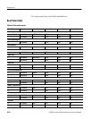
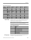
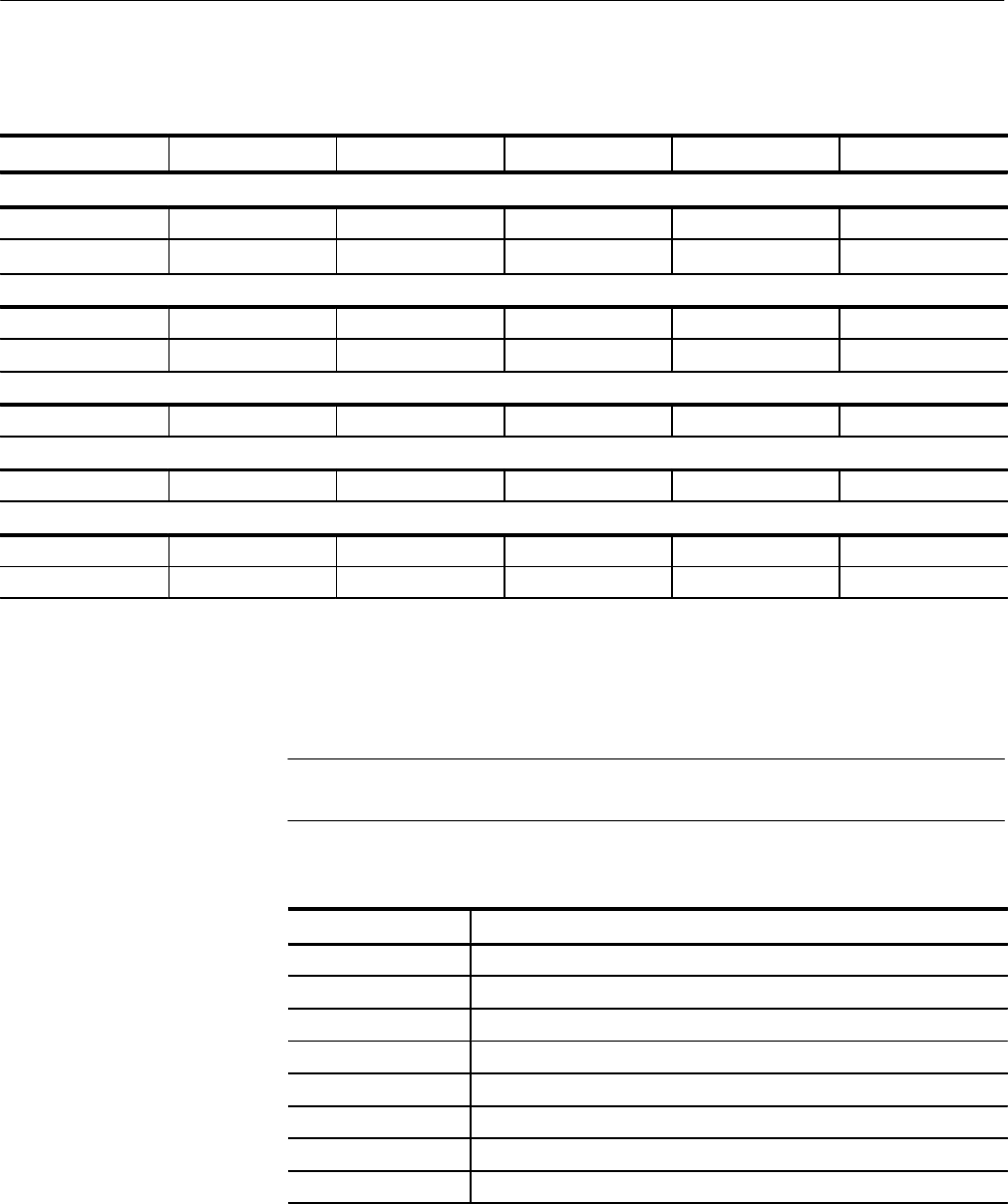
Table 6–9: Bus probe checks (cont.)
Probe Step Critical Error?Access TypeAccess SizeData to WriteProbe Address
Real Time Clock:
20 0x17000030 0x00 8-bit write No
21 0x17000030 8-bit read No
DSP-CPU Infc ASIC (Address Holding Register)
22 0x19000000 0x010560cc 32-bit write No
23 0x19000000 32-bit read No
32-bit Counter
24 0x1a000000 32-bit read No
Flash EEPROM Base Address:
25 0x20000000 32-bit read No
96k Host Infc:
26 0x60000000 0x00000000 32-bit write No
27 0x60000000 32-bit read No
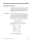
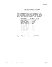
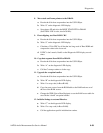
The diagnostic displays are used to troubleshoot CPU kernel problems when the
AM700 fails to boot. The segments of the diagnostic LED are turned on to
indicate the failed area as indicated in Table 6–10.
NOTE. Switch segment 2 of switch S3 on the CPU board must be in the DOWN
(Closed) position to see these values on the Diagnostic LED display.
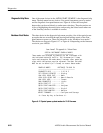
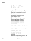
Table 6–10: Diagnostic LED definitions
LED Description
0 reserved
1 reserved
2 on : Flash EPROM (bank 0) not found
3 on : Flash EPROM (bank 1) not found
4 on : Flash EPROM (bank 2) not found
5 on : DRAM not found
6 on : battery supply failure
7 on : hardware reset active
This register is a write only octal latch which can be programmed to turn on or
off the diagnostic 7-segment LED on the CPU board.
Diagnostic Displays
LED Display Register