


3-28 Intel® PXA255 Processor Developer’s Manual
Clocks and Power Manager
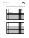
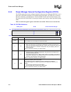
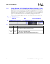
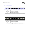
3.5.6 Power Manager GPIO Edge Detect Status Register (PEDR)
The PEDR, Table 3-12, indicates which of the GPIO pins enabled through the PWER, PRER, and
PFER registers caused a wake up from sleep mode. The bits in PEDR can only be set on a rising or
falling edge on a given GPIO pin. If PRER is set, the bits in PEDR can only be set on a rising edge.
If PFER is set, the bits in PEDR can only be set on a falling edge. To reset a bit in PEDR to zero,
write a 1 to it. The PEDR bits are reset to zero in hardware, watchdog, and GPIO resets.
This is a read/write register. Ignore reads from reserved bits. Write zeros to reserved bits.
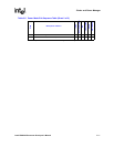
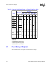
Table 3-12. PEDR Bit Definitions
0x40F0_0018 PEDR Clocks and Power Manager
Bit
31 30 29 28 27 26 25 24 23 22 21 20 19 18 17 16 15 14 13 12 11 10 9 8 7 6 5 4 3 2 1 0
Reserved
ED15
ED14
ED13
ED12
ED11
ED10
ED9
ED8
ED7
ED6
ED5
ED4
ED3
ED2
ED1
ED0
Reset 0 0 0 0 0 0 0 0 0 0 0 0 0 0 0 0 0 0 0 0 0 0 0 0 0 0 0 0 0 0 0 0
Bits Name Description
[31:16] —
Reserved.
Read undefined and must always be written with zeroes.
[15:0] EDx
Sleep mode Edge Detect Status
0 – Wake up on GPx not detected.
1 – Wake up due to edge on GPx detected.
Cleared by hardware, watchdog, and GPIO resets. Cleared by writing a 1.