


12-22 Intel® PXA255 Processor Developer’s Manual
USB Device Controller
address for the 16 x 8 data FIFO that can be used to transmit and receive data. Endpoint 0 also has
a write count register that is used to determine the number of bytes the USB host controller has sent
to Endpoint 0.
12.6.1 UDC Control Register (UDCCR)
UDCCR, shown in Table 12-12, contains seven control bits: one to enable the UDC, one to show
activity, and five to show status and associated control functions.
12.6.1.1 UDC Enable (UDE)
Enables the UDC. When UDE is set to a 1, the UDC is enabled for USB serial transmission or
reception. When UDE is set to a 0, the UDC is disabled and the UDC+ and UDC- pins are tristated.
This means that the UDC ignores all activity on the USB bus.
If UDE is set to a 0 the entire UDC design is reset. If the reset occurs while the UDC is actively
transmitting or receiving data, it stops immediately and the remaining bits in the transmit or receive
serial shifter are reset. All entries in the transmit and receive FIFO are also reset.
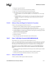
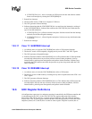
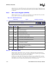
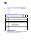
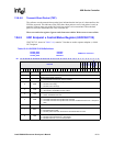
Table 12-12. UDCCR Bit Definitions
0x 4060_0000 UDCCR Read/Write and Read-Only
Bit
31 30 29 28 27 26 25 24 23 22 21 20 19 18 17 16 15 14 13 12 11 10 9 8 7 6 5 4 3 2 1 0
reserved
REM
RSTIR
SRM
SUSIR
RESIR
RSM
UDA
UDE
x x x x x x x x x x x x x x x x x x x x x x x x 1 0 1 0 0 0 0 0
Bits Name Description
31:8 — reserved
7REM
Reset interrupt mask.(read/write)
0 = Reset interrupt enabled.
1 = Reset interrupt disabled.
6RSTIR
Reset interrupt request (read/write 1 to clear).
1 = UDC was reset by the host.
5SRM
Suspend/resume interrupt mask (read/write).
0 = Suspend/resume interrupt enabled.
1 = Suspend/resume interrupt disabled.
4SUSIR
Suspend interrupt request (read/write 1 to clear).
1 = UDC received, suspend signalling from the host.
3RESIR
Resume interrupt request (read/write 1 to clear).
1 = UDC received, resume signalling from the host.
2RSM
Device Resume (read/write 1 to set)
0 = Maintain UDC suspend state
1 = Force UDC out of suspend
1UDA
UDC active (read-only).
0 = UDC currently receiving a USB reset.
1 = UDC currently not receiving a USB reset.
0UDE
UDC enable.(read/write)
0 = UDC disable.
1 = UDC enabled.