


Intel® PXA255 Processor Developer’s Manual 5-17
DMA Controller
5.3 DMAC Registers
The section describes the DMAC registers.
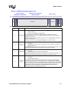
5.3.1 DMA Interrupt Register (DINT)
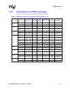
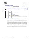
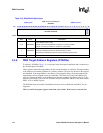
The DINT, shown in Table 5-6, logs the interrupts for each channel.
An interrupt is generated if any of these events occur:
• Any kind of transaction error on the internal bus that is associated with the relevant channel.
• The current transfer finishes successfully and the DCMD[ENDIRQEN] bit is set.
• The current descriptor loads successfully and the DCMD[STARTIRQEN] bit is set.
• The DCSR:STOPIRQEN is set to a 1 and the relevant channel is in the uninitialized or stopped
state.
Software must set the corresponding DCSR register error bit to reset the interrupt.
This is a read/write register. Ignore reads from reserved bits. Write zeros to reserved bits.
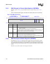
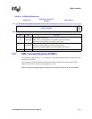
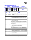
5.3.2 DMA Channel Control/Status Register (DCSRx)
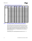
The DCSRx, shown in Table 5-7 contains the control and status bit for each channel. Read this
register to find the source of an interrupt. Write the read value back to the register to clear the
interrupt.
This is a read/write register. Ignore reads from reserved bits. Write zeros to reserved bits.
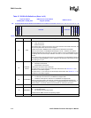
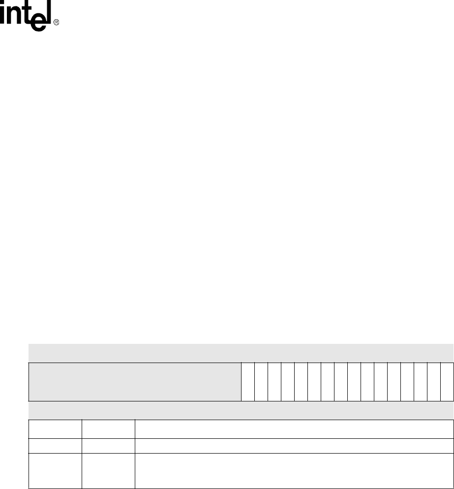
Table 5-6. DINT Bit Definitions
Physical Address
0x4000_00F0
DMA Interrupt Register (DINT) DMA Controller
Bit
31 30 29 28 27 26 25 24 23 22 21 20 19 18 17 16 15 14 13 12 11 10 9 8 7 6 5 4 3 2 1 0
reserved
ChlIntr15
ChlIntr14
ChlIntr13
ChlIntr12
ChlIntr11
ChlIntr10
ChlIntr9
ChlIntr8
ChlIntr7
ChlIntr6
ChlIntr5
ChlIntr4
ChlIntr3
ChlIntr2
ChlIntr1
ChlIntr0
Reset 0 0 0 0 0 0 0 0 0 0 0 0 0 0 0 0 0 0 0 0 0 0 0 0 0 0 0 0 0 0 0 0
Bits Name Description
31:16 — reserved
15:0 CHLINTRx
Channel ‘x’ Interrupt (read-only).
0 – No interrupt
1 – Interrupt