


10-26 Intel® PXA255 Processor Developer’s Manual
UARTs
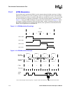
the Transmit FIFO will not be held. Only add data to the Transmit FIFO while not receiving. To
start transmission, the RCVEIR bit must be cleared.
To disable SIR, disable the IrDA LED first, if possible. Second, set the TXD GPIO pin to the
infrared LED's default state using the GPCR/GPSR registers. Next, change the TXD pin from
alternate function to GPIO mode. Now the SIR can be disabled without causing spurious transmit
pulses.
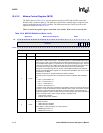
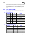
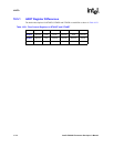
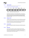
10.5 UART Register Summary
Table 10-18, Table 10-19, and Table 10-20 contain the register addresses for the FFUART,
BTUART, and STUART.
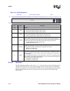
Table 10-18. FFUART Register Summary
Register Addresses
DLAB Bit
Value
Name Description
0x4010_0000 0 FFRBR Receive Buffer register (read only)
0x4010_0000 0 FFTHR Transmit Holding register (write only)
0x4010_0004 0 FFIER IER (read/write)
0x4010_0008 X FFIIR Interrupt ID register (read only)
0x4010_0008 X FFFCR FCR (write only)
0x4010_000C X FFLCR LCR (read/write)
0x4010_0010 X FFMCR MCR (read/write)
0x4010_0014 X FFLSR LSR (read only)
0x4010_0018 X FFMSR MSR (read only)
0x4010_001C X FFSPR Scratch Pad Register
0x4010_0020 X FFISR Infrared Selection register (read/write)
0x4010_0000 1 FFDLL Divisor Latch Low register (read/write)
0x4010_0004 1 FFDLH Divisor Latch High register (read/write)
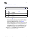
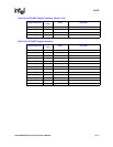
Table 10-19. BTUART Register Summary (Sheet 1 of 2)
Register Addresses
DLAB Bit
Value
Name Description
0x4020_0000 0 BTRBR Receive Buffer register (read only)
0x4020_0000 0 BTTHR Transmit Holding register (write only)
0x4020_0004 0 BTIER IER (read/write)
0x4020_0008 X BTIIR Interrupt ID register (read only)
0x4020_0008 X BTFCR FCR (write only)
0x4020_000C X BTLCR LCR (read/write)
0x4020_0010 X BTMCR MCR (read/write)
0x4020_0014 X BTLSR LSR (read only)
0x4020_0018 X BTMSR MSR (read only)