


Intel® PXA255 Processor Developer’s Manual 3-1
Clocks and Power Manager 3
The Clocks and Power Manager for the PXA255 processor controls the clock frequency to each
module and manages transitions between the different power manager (PM) operating modes to
optimize both computing performance and power consumption.
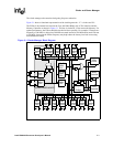
3.1 Clock Manager Introduction
The Clocks and Power Manager provides fixed clocks for each peripheral unit. Many of the
devices’ peripheral clocks can be disabled using the Clock Enable Register (CKEN), or through
bits in the peripheral’s control registers. To minimize power consumption, turn off the clock to any
unit that is not being used. The Clocks and Power Manager also provides the programmable-
frequency clocks for the LCD Controller, Memory Controller, and CPU. These clocks are related to
each other because they come from the same internal Phase Locked Loop (PLL) clock source. To
program the PLL’s frequency, follow these steps (for information on the factors L, M, and N, see
Section 3.6.1, “Core Clock Configuration Register (CCCR)” on page 3-34):
1. Determine the fastest synchronous memory requirement (SDRAM frequency).
2. If the SDRAM frequency is less than 99.5 MHz, the Memory Frequency must be twice the
SDRAM Frequency and the SDRAM clock ratio in the Memory Controller must be set to two.
If the SDRAM frequency is 99.5 MHz, the Memory Frequency is equal to the SDRAM
frequency.
3. Round the Memory Frequency down to the nearest value of 99.5 MHz (L = 0x1B), 118.0 MHz
(L = 0x20), 132.7 MHz (L = 0x24), 147.5 MHz (L = 0x28), or 165.9 MHz (L = 0x2D), and
program the value of L in the Core Clock Configuration register. This frequency (or half, if the
SDRAM clock ratio is 2) is the External Synchronous Memory Frequency.
4. Determine the required Core Frequency for normal (Run Mode) operation. This mode is used
during normal processing, when the application must make occasional fetches to external
memory. The possible values are one, two, or four times the Memory Frequency. Program this
value (M) in the Core Clock Configuration register.
5. Determine the required Core Frequency for Turbo Mode operation. This mode is generally
used when the application runs entirely from the caches, because any fetches to external
memory slow the Core’s performance. This value is a multiple (1.0, 1.5, 2.0, or 3.0) of the Run
Mode Frequency. Program the value (N) in the Core Clock Configuration register.
6. Configure the LCD Controller and Memory Controller for the new Memory Frequency and
enter the Frequency Change Sequence (described in Section 3.4.7, “Frequency Change
Sequence” on page 3-11).
Note: Not all frequency combinations are valid. See Section 3.3.3, “Core Phase Locked Loop” for valid
combinations.