Intel® PXA255 Processor Developer’s Manual 11-7
Fast Infrared Communication Port
When the transmit FIFO has 32 or more empty bytes, the transmit DMA request and an interrupt (if
enabled) are generated and tell the processor to send more data to the FIFO. When the transmit
FIFO is full, any more data from the processor is lost. When the receive FIFO reaches its trigger
level (programmed in ICCR2), the receive DMA request (if no errors are found within the entries)
and an interrupt (if enabled) are generated and tell the processor to remove the data from the FIFO.
If an error is found in the FIFO’s trigger level range, DMA requests are disabled and an interrupt is
generated to ensure that the DMAC does not read the error bytes.
The number of bytes being transferred for each DMA request is programmed in the DMAC and
can be 8, 16, or 32 bytes. The receive FIFO’s trigger level must be set so the FIFO has enough data
for the DMAC to read. The transmit FIFO does not have programmable trigger levels. Its DMA
request is generated when the FIFO has 32 or more empty bytes, regardless of the DMA transfer
size.
The DMA controller must not service the receive FIFO when the processor tries to respond to a
receive error interrupt. The error interrupt may be set high before the DMA controller finishes the
previous request. The processor can not remove the error bytes until the DMAC has completed its
transaction.
11.2.11 Trailing or Error Bytes in the Receive FIFO
When the number of bytes in the receive FIFO is less than the trigger level and no more data is
being received, the bytes in the FIFO are called trailing bytes. Trailing bytes do not trigger a
receive DMA request. Instead they trigger the end/error in FIFO, ICSR0[EIF] interrupt, which is
nonmaskable. When ICSR0[EIF] is set, DMA requests are disabled. The core must read bytes from
the FIFO until ICSR0[EIF] is cleared.
The core must also read bytes from the FIFO until ICSR0[EIF] is cleared if there are errors in FIFO
entries below the DMA trigger level. When the entries below the DMA trigger level no longer
contain status flags, DMA requests are enabled.
11.3 FICP Register Definitions
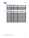
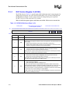
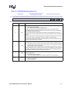
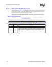
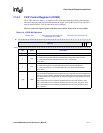
The FICP has six registers: three control registers, one data register, and two status registers. The
FICP registers are 32 bits wide, but only the lower 8 bits have valid data. The FICP does not
support byte or half-word operations. CPU reads and writes to the FICP registers must be word
wide.
The control registers determine: IrDA transmission rate, address match value, how transmit FIFO
underruns are handled, normal or active low transmit and receive data, whether transmit and
receive operations are enabled, the FIFO interrupt service requests, receive address matching, and
loopback mode.
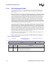
The data register addresses the top of the transmit FIFO and the bottom of the receive FIFO. Reads
to the data register access the receive FIFO. Writes to the data register access the transmit FIFO.
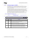
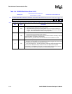
The status registers contain: CRC, overrun, underrun, framing, and receiver abort errors; the
transmit FIFO service request; the receive FIFO service request; and end-of-frame conditions.
Each of these hardware-detected events signals an interrupt request to the interrupt controller. The
status registers also contain flags for transmitter busy, receiver synchronized, receive FIFO not
empty, and transmit FIFO not full (no interrupt generated).


