


4-22 Intel® PXA255 Processor Developer’s Manual
System Integration Unit
After a reset, the FIQ and IRQ interrupts are disabled within the CPU, and the states of all of the
interrupt controller registers are set to 0x0. The interrupt controller registers must be initialized by
software before interrupts are again enabled within the CPU.
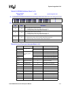
4.2.2.1 Interrupt Controller Mask Register (ICMR)
The ICMR, shown in Table 4-30, contains one mask bit per pending interrupt bit (22 total). The
mask bits control whether a pending interrupt bit generates a processor interrupt (IRQ or FIQ).
When a pending interrupt becomes active, it is only processed by the CPU if the corresponding
ICMR mask bit is set to 1. While in Idle mode, ICCR[DIM] must be set for the mask to be
effective, otherwise any interrupt source that makes a request sets the corresponding pending bit
and the interrupt is automatically processed, regardless of the state of its mask bit.
Mask bits allow periodic software polling of interruptible sources while preventing them from
actually causing an interrupt. The ICMR is initialized to zero at reset, indicating that all interrupts
are masked and the ICMR has to be configured by the user to select the desired interrupts.
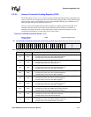
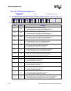
Table 4-36 describes the available first-level interrupts and their location in the ICPR.
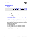
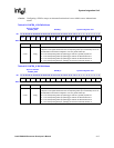
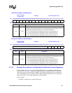
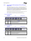
4.2.2.2 Interrupt Controller Level Register (ICLR)
The ICLR register, shown in Table 4-31, controls whether a pending interrupt generates an FIQ or
an IRQ interrupt. If a pending interrupt is unmasked, the corresponding ICLR bit field is decoded
to select which processor interrupt is asserted. If the interrupt is masked, then the corresponding bit
in the ICLR has no effect. At reset the ICLR is initialized to all zeros, and software must configure
the ICLR to reflect the normal operation value.
Table 4-36 describes the available first-level interrupts and their location in the ICPR.
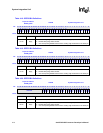
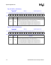
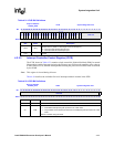
Table 4-30. ICMR Bit Definitions
Physical Address
0x40D0_0004
ICMR System Integration Unit
Bit
31 30 29 28 27 26 25 24 23 22 21 20 19 18 17 16 15 14 13 12 11 10 9 8 7 6 5 4 3 2 1 0
IM31
IM30
IM29
IM28
IM27
IM26
IM25
IM24
IM23
IM22
IM21
IM20
IM19
IM18
IM17
reserved
reserved
IM14
IM13
IM12
IM11
IM10
IM9
IM8
reserved
Reset
0 0 0 0 0 0 0 0 0 0 0 0 0 0 0 0 0 0 0 0 0 0 0 0 ? ? ? ? ? ? ? ?
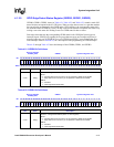
Bits Name Description
<31:8> IM[x]
Interrupt Mask ‘x’ (where x= 8 through 14 and 17 through 31).
0 – Pending interrupt is masked from becoming active (interrupts are NOT sent to CPU
or Power Manager).
1 – Pending interrupt is allowed to become active (interrupts are sent to CPU and Power
Manager).
NOTE: In idle mode, the IM bits are ignored if ICCR[DIM] is cleared.
<7:0> — reserved