


Intel® PXA255 Processor Developer’s Manual 4-27
System Integration Unit
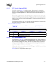
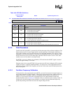
<9> IS9
GPIO[1] Edge Detect Interrupt Pending
0 – Interrupt NOT pending due to edge detect on GPIO[1].
1 – Interrupt pending due to edge detect on GPIO[1].
<8> IS8
GPIO[0] Edge Detect Interrupt Pending
0 – Interrupt NOT pending due to edge detect on GPIO[0].
1 – Interrupt pending due to edge detect on GPIO[0].
<7> IS7
Hardware UART Service Request Interrupt Pending
0 – Interrupt NOT pending due to Hardware UART Service Request.
1 – Interrupt pending due to Hardware UART Service Request.
<6:0> — reserved
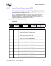
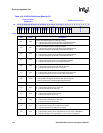
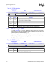
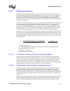
Table 4-36. List of First–Level Interrupts (Sheet 1 of 2)
Bit Position Source Unit # of Level 2 Sources Bit Field Description
IS<31>
Real-time clock
1 RTC equals alarm register.
IS<30> 1 One Hz clock TIC occurred.
IS<29>
Operating system
timer
1 OS timer equals match register 3.
IS<28> 1 OS timer equals match register 2.
IS<27> 1 OS timer equals match register 1.
IS<26> 1 OS timer equals match register 0.
IS<25> DMA controller 16 DMA Channel service request.
IS<24>
Synchronous Serial
Port
3 SSP service request.
IS<23> MUlti Media Card 9 MMC status / error detection
IS<22> FFUART 5 x-mit, receive, error in FFUART.
IS<21> BTUART 5 x-mit, receive, error in BTUART
IS<20> STUART 4 x-mit, receive, error in STUART
IS<19> ICP 6 x-mit, receive, error in ICP.
IS<18> I2C 6 I2C service request.
IS<17> LCD controller 15 LCD controller service request.
IS<16> Network SSP 4 Network SSP service request
IS<15> reserved
IS<14> AC97 10 AC97 interrupt
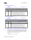
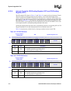
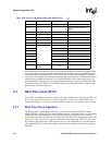
Table 4-35. ICPR Bit Definitions (Sheet 3 of 3)
Physical Address
0x40D0_0010
ICPR System Integration Unit
Bit
31 30 29 28 27 26 25 24 23 22 21 20 19 18 17 16 15 14 13 12 11 10 9 8 7 6 5 4 3 2 1 0
IS31
IS30
IS29
IS28
IS27
IS26
IS25
IS24
IS23
IS22
IS21
IS20
IS19
IS18
IS17
reserved
IS14
IS13
IS12
IS11
IS10
IS9
IS8
reserved
Reset 0 0 0 0 0 0 0 0 0 0 0 0 0 0 0 0 0 0 0 0 0 0 0 0 0 0 0 0 0 0 0 0
Bits Name Description