


Intel® PXA255 Processor Developer’s Manual 17-9
Hardware UART
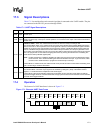
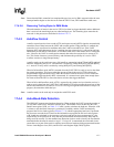
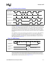
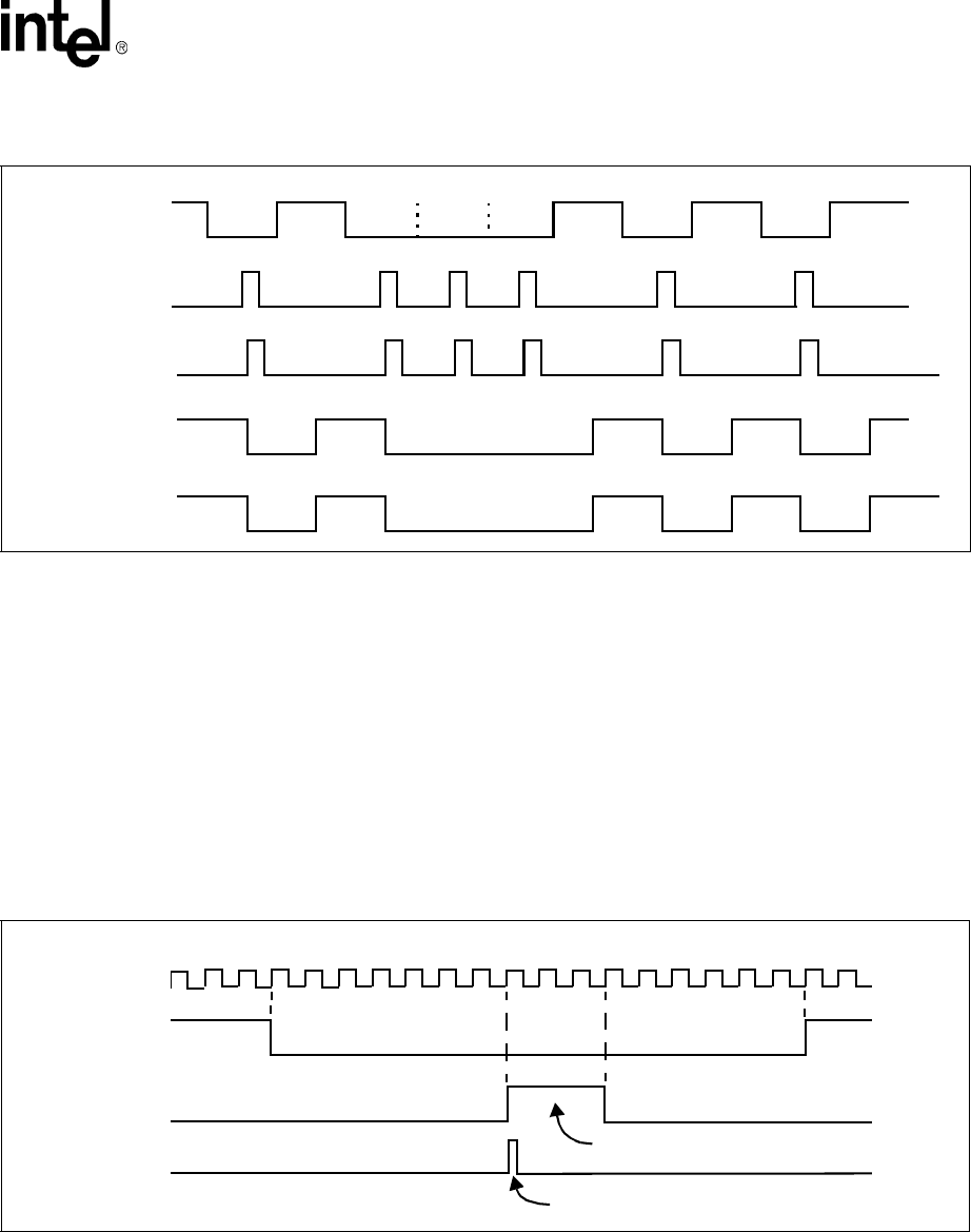
The top line in Figure 17-3 shows an asynchronous transmission as it is sent from the UART. The
second line shows the pulses generated by the IR encoder at the TXD pin. A pulse is generated in
the middle of the START bit and any data bit that is a zero. The third line shows the values received
at the RXD input pin. The fourth line shows the receive decoder’s output. The receive decoder
drives the receiver data line low when it detects a pulse. The bottom line shows how the UART’s
receiver interprets the decoder’s action. This last line is the same as the first, but it is shifted half a
bit period.
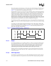
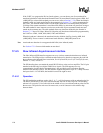
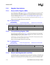
When XMODE is cleared, each zero bit has a pulse width of 3/16 of a bit time. When XMODE is
set, a pulse of 1.6 µs is generated in the middle of each zero bit. The shorter infrared pulse
generated when XMODE is set reduces the LED’s power consumption. At 2400 bps, the LED is
normally on for 78 µs for each zero bit that is transmitted. When XMODE is set, the LED is on
only 1.6 µs (as show in Figure 17-4).
To prevent transmitter LED reflection feed back to the receiver, disable the IR receiver decoder
when the IR transmit encoder transmits data and disables the IR transmit encoder when the IR
receiver decoder receives data. The RCVEIR and XMITIR bits in the Infrared Selection Register
(ISR) must not be set at the same time (refer to Section 17.5.15).
Figure 17-3. IR Transmit and Receive Example
START
BIT
STOP
BIT
10001
0
10
START
BIT
10001
0
10
TRANSMIT
IR
ENCODER OUTPUT
IR DECODER OUTPUT
UART
UART RECEIVE
(TXD PIN VALUE)
SHIFT VALUE
RXD PIN VALUE
SHIFT VALUE
STOP
BIT
Figure 17-4. XMODE Example.
1
7
11 16
1.6
µ
s
3 16X BAUD Clock periods
IR_TXD Pin value
XMODE = 1
IR_TXD Pin value
XMODE = 0
Transmit Start bit
followed by 1
16X Baud Clock