


Intel® PXA255 Processor Developer’s Manual 8-9
Synchronous Serial Port Controller
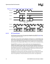
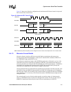
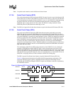
8.7.1.1 Data Size Select (DSS)
The 4-bit data size select (DSS) field is used to determine the size of the data that the SSPC
transmits and receives. The data can range from 4 to 16 bits in length. When data is programmed to
be less than 16 bits, received data is automatically right-justified and the upper bits in the receive
FIFO are zero-filled by receive logic. Do not left-justify transmit data before placing it in the
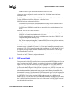
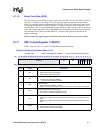
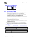
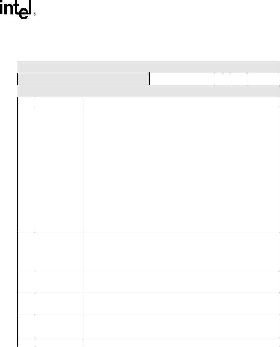
Table 8-2. SSCR0 Bit Definitions
0x4100_0000 SSP Control Register 0 (SSCR0) Synchronous Serial Port Controller
Bit
31 30 29 28 27 26 25 24 23 22 21 20 19 18 17 16 15 14 13 12 11 10 9 8 7 6 5 4 3 2 1 0
reserved SCR
SSE
ECS
FRF
DSS
Reset
X 0x00 0 0 0 0
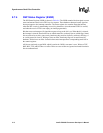
Bits Name Description
3:0
DSS
Data Size Select
0000 - reserved, undefined operation
0001 - reserved, undefined operation
0010 - reserved, undefined operation
0011 - 4-bit data
0100 - 5-bit data
0101 - 6-bit data
0110 - 7-bit data
0111 - 8-bit data
1000 - 9-bit data
1001 - 10-bit data
1010 - 11-bit data
1011 - 12-bit data
1100 - 13-bit data
1101 - 14-bit data
1110 - 15-bit data
1111 - 16-bit data
5:4 FRF
Frame Format
00 - Motorola’s Serial Peripheral Interface (SPI)
01 - Texas Instruments’ Synchronous Serial Protocol (SSP)
10 - National Microwire
11 - reserved, undefined operation
6ECS
External clock select:
0 = On-chip clock used to produce the SSP’s serial clock (SSPSCLK).
1 = SSPEXTCLK is used to create the SSPSCLK.
7 SSE
Synchronous Serial Port Enable:
0 = 0 - SSP operation disabled (pins may function as GPIOs)
1 = 1 - SSP operation enabled
15:8 SCR
Serial Clock Rate
Value (0 to 255) used to generate transmission rate of SSP.
Bit rate = 3.6864x10
6
/ (2 x (SCR + 1)) or SSPEXTCLK / (2 x (SCR + 1))
31:16 — reserved