


16-24 Intel® PXA255 Processor Developer’s Manual
Network SSP Serial Port
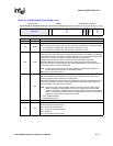
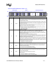
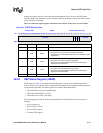
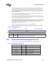
16.5.4 SSP Time Out Register (SSTO)
The SSTO register, shown in Table 16-6,specifies the time-out value used to signal a period of
inactivity within the receive FIFO.
This is a read/write registers. Ignore reads from reserved bits. Write zeros to reserved bits.
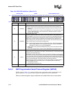
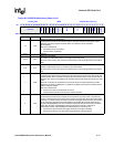
16.5.5 SSP Interrupt Test Register (SSITR)
SSITR, shown in Table 16-7 on page 16-25, contains bit fields used for testing purposes only.
Setting bits in this register causes the SSP controller to generate interrupts and DMA requests if
enabled. This is useful in testing the port’s functionality.
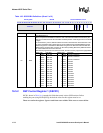
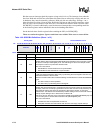
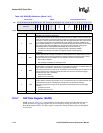
1:0 SCMODE
SERIAL BIT-RATE CLOCK MODE:
Selects one of four serial clock modes when the PSP is selected (SSCR0[FRF]=0b11).
Its operation is similar to how SSCR1[SPO] and SSCR1[SPH] together determine the idle state
of SSPSCLK and on which edges data is driven and sampled.
0b00 - Data Driven (Falling), Data Sampled (Rising), Idle State (Low)
0b01 - Data Driven (Rising), Data Sampled (Falling), Idle State (Low)
0b10 - Data Driven (Rising), Data Sampled (Falling), Idle State (High)
0b11- Data Driven (Falling), Data Sampled (Rising), Idle State (High)
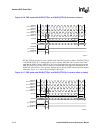
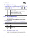
Table 16-5. SSPSP Bit Definitions (Sheet 2 of 2)
0x4140_002C SSPSP Network SSP Serial Port
Bit
31 30 29 28 27 26 25 24 23 22 21 20 19 18 17 16 15 14 13 12 11 10 9 8 7 6 5 4 3 2 1 0
reserved
DMYSTOP
reserved
SFRMWDTH SFRMDLY
DMYSTRT
STRTDLY
ETDS
SFRMP
SCMODE
Reset ? ? ? ? ? ? ? 0 0 ? 0 0 0 0 0 0 0 0 0 0 0 0 0 0 0 0 0 0 0 0 0 0
Bits Name Description
Table 16-6. SSTO Bit Definitions
0X4140_0028 SSTO Network SSP Serial Port
Bit
31 30 29 28 27 26 25 24 23 22 21 20 19 18 17 16 15 14 13 12 11 10 9 8 7 6 5 4 3 2 1 0
reserved TIMEOUT
Reset
? ? ? ? ? ? ? ? 0 0 0 0 0 0 0 0 0 0 0 0 0 0 0 0 0 0 0 0 0 0 0 0
Bits Name Description
31:24 — reserved
23:0 TIMEOUT
TIMEOUT:
Value used to set the time-out interval. When the TIMEOUT value is cleared, no time-out occurs
and SSSR[TINT] is not set.
The time-out interval is given by the equation: Time-out Interval = (TIMEOUT) / Peripheral Clock
Frequency